
1. introduction
This article refers to the address: http://
The battery is the key power output unit of electric vehicles. In the common batteries such as lead-acid batteries, nickel-cadmium batteries, nickel-hydrogen batteries, lithium batteries and fuel cells, it has low energy ratio, light weight, good temperature characteristics and low pollution. The memory effect is not obvious, and the nickel-hydrogen battery is widely used in electric vehicles. However, due to the incorrect charging method, the service life of the rechargeable battery is far below the specified life. That is to say, many batteries are not used up, but are burnt. It can be seen that the quality of the charger has a great impact on battery life. Based on this, this paper proposes a design scheme of smart charger using 3-stage charging control scheme, which can effectively improve charging efficiency and extend battery life.
2. Introduction to control methods
Commonly used charge termination control methods include: timing control method, voltage control method, current control method and integrated control method.
The timing control method refers to using the timing system to control the entire charging time. When the time is not fixed, the battery is stopped. Stop charging. Commonly used voltage control methods include the highest voltage method (Vmax), the voltage negative increment method (△V), and the zero voltage increment method (0△V). The commonly used temperature control methods include the highest temperature method (Tmax), and the temperature rise method. (△T). Temperature change rate (ΔT/Δt), the lowest temperature method (Tmin). The integrated control method refers to the combination of several control methods in the above control methods.
Compared with the traditional three-stage charging theory of constant voltage and constant current charging, the charging efficiency of the battery can be greatly improved. The three-stage charging adopts first constant current charging, constant voltage charging, and finally floating charging. If the battery is in a deep discharge state before charging, it is also pre-charged before charging.
3. System hardware
3.1 Overall hardware design
The charging object is a nickel-hydrogen battery, and the method of voltage and current feedback is adopted to achieve the purpose of constant current and constant voltage charging, and at the same time, various parameters in the charging process are detected and controlled. The overall design of the charger is shown in Figure 1.
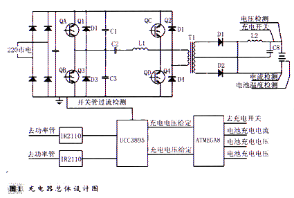
In this scheme, the maximum output power of the switching power supply is 2.4KW, and the AC input range is 1 76V-264V. The charger circuit mainly includes two parts: the main charging circuit and the auxiliary control circuit. The working process of the whole circuit is: 220V single-phase alternating current The full-bridge rectification is filtered by a capacitor to obtain a DC power of about 300V. After passing through an inverter bridge composed of 4 IGBTs, a high-frequency alternating current is obtained, coupled to the secondary side via a high-frequency transformer, and then rectified by a rectifier D1, D2, and finally After being filtered by the inductor L 2 and the capacitor C8, a stable DC output is obtained. Due to the three-stage charging, the charging voltage and charging current are different at each stage. Therefore, ATMEGA8 single-chip microcomputer is used as the charging process control device. When charging, the single-chip microcomputer detects the charging current of the rechargeable battery, the charging voltage, the battery temperature, prevents the circuit from overvoltage and overcurrent, and the battery temperature is too high. It can also determine whether the battery voltage and current values ​​are used to determine whether Switch to the next charging phase. At the same time, the voltage value or current value of each stage of charging is given by the single-chip microcomputer, and compared with the corresponding voltage and current value obtained by sampling, the phase-change control chip UCC3895 is used to change the PWM value to change the conduction time of the power tube. The purpose of obtaining different stable output values ​​at different stages.
3.2 Introduction of main charging circuit
The main charging circuit uses a full bridge inverter circuit. The H-bridge consists of four IGBT tubes Q1 Q2 Q3 Q4. The leading bridge arm composed of Q1 and Q4 realizes zero voltage conduction and shutdown, and the hysteresis bridge arm composed of Q2 and Q3 realizes zero current conduction and shutdown. During operation, the driving voltages of Q1 and Q2 are reversed, and the driving voltages of Q 3 and Q 4 are also reversed. The dead time of Q 1 and Q 2 and Q 3 and Q 4 during the on-switching can be changed by the phase shift controller. The UCC389S controls the duty cycle by adjusting the Q4 phase shift to adjust the common conduction time of the leading bridge arm to achieve the purpose of changing the output power. The adjustment principle of the hysteresis bridge arm composed of Q2 and Q3 is the same as that of the leading bridge arm.
The UCC3895 is a new generation of advanced BICMOS phase-shifted PWM controllers that maintain the main functions of the UCC3875/6/7/8/9 family of ICs with new enhanced control logic, adaptive delay setting and shutdown. performance. The UCC3895 utilizes the corresponding phase shift between the two half-bridge switches to achieve full-bridge power stage control. It achieves or has high efficiency at high frequency conditions using stable frequency pulse width modulation and resonant zero voltage switching techniques. The UCC3895 can be used both as a voltage mode controller and as a current mode controller. UCC389 5 has programmable turn-on delay programmable, adaptive delay setting, can work in voltage and current mode, soft start / soft stop programmable, 0 -100% duty cycle adjustable, 1M maximum clock frequency and other characteristics .
3.3 Introduction to auxiliary control
The charging control circuit uses ATmega8 microcontroller for data acquisition and control. The chip is an enhanced RISC structure low-power 8-bit microcontroller with data throughput of 1 MI PS/MHz, 8-byte Flash program memory, erase and write times. More than 1 000 times, support for online programming (1 SP), greatly facilitates the debugging and modification of the program. With six 10-bit ADCs and two 8-bit ADCs, eight single-ended input voltages from port PORTC can be sampled. 6-channel PWM, on-chip programmable watchdog timer, greatly simplifies the peripheral design of the control circuit and ensures the safe operation of the program. The ADC is responsible for the collection of voltage, current, and temperature data during charging, and the reference value of the voltage and current during charging of the PWM output to the comparison. Road, while the single-chip control switching power supply control module UCC3895.
Voltage detection circuit: The voltage sampling circuit is composed of a precision resistor and an adjustable resistor. The maximum setting range of the AD measurement of the single chip microcomputer is 5v. Therefore, the battery pack voltage should be scaled down to a range of 5 V, and then converted using the ADEGA function of the ATMEGA8, which can achieve an accuracy of 0.1 V. The single-chip microcomputer internally calculates the battery voltage by subtraction. The circuit adopts the internal 10-bit AD conversion of the single-chip microcomputer, which reduces the complexity of the design circuit and improves the reliability and precision. In order to resist electrical interference and high-voltage electric shock, the circuit Isolated with a high speed isolation diaphragm PC81 7 .
Current detection circuit: Generally, when the current is collected, a sampling resistor with a small resistance value is connected in series in the circuit, and the voltage on the sampling resistor is input into the single-chip conversion channel for A/D conversion, and then the voltage value is converted into a current value by calculation. However, due to the large charging current in this scheme, the use of resistor sampling consumes a lot of power, and can be sampled using a current transformer.
Temperature detection circuit: temperature sampling temperature sensor DS l 8B 2 0, which has greatly improved the temperature measurement accuracy, conversion time, transmission distance, resolution, etc., and brings more convenient use to the user. And more satisfactory results. There are two ways to connect to the system, one is parasitic power supply, and the other is external power supply. The latter is used here.
3.4 Introduction to the work process
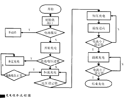
After power-on, the MCU first checks whether the battery is connected reversely, and whether the battery voltage is too low due to electricity. If the voltage is too low, first use a small current to charge the battery, so that the voltage reaches the three-stage charging level and starts charging. Usually enter the normal charging stage directly. The first is the constant current charging stage. The charging is less than 0.5 C. Generally, 0.1 C is taken, and the voltage will rise slowly. When the voltage reaches a certain stage (in this case, 60V is used), it is changed to constant. Pressure charging, at this time, the internal resistance of the battery will increase according to the electric process, and the charging current will decrease with the internal resistance. When the detection current of the single-chip microcomputer is reduced to a certain value (less than 1/1 of the constant current charging value) ), immediately transfer to the trickle charge phase, the charge current is generally taken to 0.3C, at this stage the battery voltage will decrease, when the charge current is less than 0.01 C, the battery can be considered full, the microcontroller will automatically remove the battery from Cut off in the charging circuit. In the constant voltage phase, if the single-chip microcomputer detects that the battery temperature is higher than 45 degrees, it will automatically transfer to the third stage, and then turn to the second stage after the temperature drops. After being fully charged, turn off the relay through the MCU and stop charging. .
4. System software design
The software flow block diagram is shown in Figure 2.
The system software is written in C language, compiled in ICCAVR environment, and debugged in AV Rstudio4 environment. In the process of programming software, although the control method of constant voltage after constant current is relatively simple, it is necessary to fully consider the line voltage drop between the detection point of the output voltage of the charger and the battery end. Therefore, in the process of continuously reducing the charging current, only the balance between the output voltage of the charger and the line voltage drop can be controlled to make the voltage at the battery terminal constant.
5. Conclusion
With the development of electric vehicle technology, the use of nickel-hydrogen battery is more and more extensive, and it is urgent to extend the battery charging life. With the proper charging method, the service life of the battery can be increased by about 25% compared with the ordinary charging method. The charger can realize the high current charging of the nickel-hydrogen battery, and the automatic control of the charging process to protect and protect the battery. It is very suitable for use as an on-board charger for electric vehicles, and has a broad promotion prospect.
Home Using Solar Charger Controller use high-end shell which make of ABS engineering plastics. It has high strengh impact resistance. Heat-sink bottom desighned in line with aerodynamics is made of aviation aluminium materials. The wide cross-sectional are design connector makes connection easier.With our strict quality control, our home using Solar Charger Controller helps you build a sweet home.
Home Using Solar Charger Controller
Inverter Charger,Home Using Solar Charger Controller,Home Solar System Mppt Controller,Home Solar Systems Charge Controller
Guangzhou City Poojin Electronic Technology Co., Ltd. , https://www.inverter-belttt.com