
With the rapid development of the automotive industry, the demand for automotive recorders has also multiplied. The car recorder, also known as the "car black box", can completely and accurately record various information under the driving state of the car [1], can completely record the car's driving track, braking performance, switch signal, and can be as needed Recall data for analysis or reproduce on a computer with dedicated software. It is considered to be an effective means of ensuring vehicle safety, and it can quickly obtain relevant driving data, improve operational status, and become an indispensable equipment for vehicle traffic management. As an important part of the car recorder, the data acquisition system is directly related to the performance of the recorder, and has a great impact on the overall function of the recorder.
This article refers to the address: http://
1 hardware circuit structure
1.1 Real Time Clock Module
Since the various data and records generated by the system are closely related to time, the real-time requirements of the clock are very high, and the recorder itself has the danger of power failure. In order to accurately record the running state of the vehicle and record the abnormal situation, Select the real-time clock chip to provide the date and time. The real-time clock chip is a permanent clock circuit that not only supports daily time updates, but also enables date updates [2]. This article uses DALLAS's DS1302 chip, which has high performance, low power consumption, and easy clock calibration. It is powered by 3V lithium battery and in-vehicle battery, which can guarantee that the clock chip can still be in case of battery failure. Working properly, so that the data of the recorder is equally accurate and reliable. Its internal 31B static RAM, storage capacity to meet the needs of the application. Data is serially input on the rising edge of CLK. When a single-byte or multi-byte transfer is made, the first byte that begins is the command byte, which specifies which of the 31 bytes will be accessed. When any data transfer is made, its most significant bit MSB (bit 7) must be a logic one, and if it is zero, writing to the DS1302 is prohibited. The clock circuit is shown in Figure 1. Vcc1 is connected to the 3V lithium battery, Vcc2 is connected to the battery, and the 5, 6, and 7 pins are respectively connected to the clock terminal, data terminal and reset terminal of the S3C2410, and the clock module is performed by the main controller S3C2410. Unified management.

1.2 Vehicle speed acquisition module
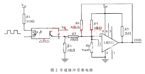
The recorder continuously detects the speed of the vehicle from the start of the vehicle and saves it in real time. Speed ​​is an analog variable that changes from moment to moment. The vehicle speed signal is input by pulse in the form of a pulse. In order to prevent the surrounding environment and its own interference, a single optocoupler chip TLP521 is used to cut off the direct electrical signal connection between the input and output channels, mainly by electro-optical-electrical conversion. Isolation. By shielding and optocoupler isolation, a clean signal is obtained. In order to obtain a good rectangular wave and make the vehicle speed measurement reach a certain precision, the system uses Schmitt trigger LM311 to complete the waveform shaping. After the signal acquisition function is completed, the collected signal needs to be sent to the programmable logic device for further processing. Then, it is sent to the main chip S3C2410, and all interference signals should be minimized before entering the main controller. In the actual control process, various interference signals are unavoidable. In order to eliminate or reduce the control effect of the interference signal on the system as much as possible, in addition to taking measures in the system hardware and environment, certain measures are also taken in the control algorithm. To suppress the influence of the interference signal, it is filtered in the program by successively sampling and averaging [3]. The hardware circuit of the vehicle speed pulse acquisition module is shown in Figure 2.
1.3 Switch Acquisition Module
Switching signals include directional lights, reversing lights, doors, high beam lights, low beam lights, brakes, horns, vehicle start-ups, etc. These are important digital switches, which are collected and saved for post-analysis. Great help [4]. These signals can be input through the I/O port of the ARM chip. However, these signals are high-voltage signals. Direct connection to the ARM board may damage the CPU. The optocoupler chip TLP521 is used to isolate them to avoid CPU damage. In the S3C2410, the GPIO pin usage function can be set by the GPnCON (n is the I/O port group number) register. The system collects the binary signal every 0.2s, and the collected switching quantity can be read from the GPnDAT register. The chip's interface is a 4-pin SPI, which greatly reduces the number of pins the processor needs to provide [5]. When the state of any of the digital input signals changes, the main processor is notified by means of an interrupt, thereby reducing the burden of frequent query by the processor. Figure 3 is a circuit switching signal acquisition circuit, and other switching circuit is the same.
2 software design
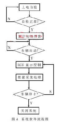
After the data acquisition system software of the recorder requires power-on reset, first perform self-test; then display the initial interface (including current time, driving speed, etc.); finally, judge whether the car starts according to the number of pulses transmitted by the speed sensor and the duration. If it is not started, it will return. If it is started, it will enter the detection of each data amount. The recorder software design includes display, speed acquisition, real-time clock, digital acquisition, data transmission, etc. The acquisition system software flow chart is shown in Figure 4.
The main function of the car recorder initialization function is to assign the device number to the device. The device access is performed through a fixed set of entry points. The interface function is defined by the file_operations structure. The car recorder mainly includes the following members:
Static int _ _init s3c2410_ts_init (void)
{ ... ...
Ret = register_chrdev(0,DEVICE_NAME, &s3c2410_fops);};
Static struct file_operations s3c2410_fops = {
Owner: THIS_MODULE,
/* Pointer to the module that owns the structure */
Open: s3c2410_ts_open, /*Open the device*/
Read: s3c2410_ts_read, /* used to read data from the device */
Release: s3c2410_ts_release,
This operation will be called when the /*file structure is released.
Poll: s3c2410_ts_poll,
/* is used to query whether read or write will be blocked */
}; Finally, you need a cleanup function that unregisters the interface before the module is removed and returns all resources to the system.
Static void _ _exit s3c2410_ts_exit (void)
{ ......
Unregister_chrdev(tsMajor, DEVICE_NAME);
...... };
Let the speed measurement function be void mk_int()(void)interrupt(). Measuring the speed of a car is actually measuring the rectangular pulse width produced by the car's speed sensor. After measuring the width of the pulse, the traveling speed of the car is then obtained according to formula (1).
K=(convert/(number*wave_width*co))*(real_speed/display_speed) (1)
Among them, number represents the number of pulses generated by the speed sensor in one revolution, wave_width represents the width of each pulse low level, co represents the number of revolutions of the vehicle per 1km speed sensor, real_speed is the nominal speed of the vehicle, used to correct system errors , display-speed is the measured speed of the vehicle, used to correct the system error, convert is the conversion coefficient of the vehicle speed, which is related to the crystal oscillation frequency of the system. Other related procedures are as follows:
(1) extern void flash_clear( ) extern void s3c2410_4k_clear( ) clears everything in the S3C2410 memory and real-time clock chip, which is only used during factory initialization [6].
(2) extem void accident_time_record( ) records the time of each PC upload and download operation.
(3) void accident_deal (void) illegal shutdown handler [7]. During the operation of the recorder, there is a possibility of artificial or non-human power-off. In this case, in order to ensure that the illegal shutdown does not lose data, during the entire program operation, some important aspects of the vehicle operating state are described. The data is stored in the S3C2410. When the recorder is powered on, it can be restored to the state of the last illegal shutdown according to the data [8].
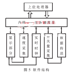
The system exchanges human and machine through LCD. The basic functions displayed are as follows: (1) void init_lcd( ) LCD initialization program; (2) void write_cmd (unsigned char cmd) Write instruction to instruction register to control explicit mode, set Display the address of the register; (3) void write_hc (unsigned int word) write 8-bit data to the display register, that is, display the half-width ASCII code character of 16×8 dot matrix; (4) void write_word (unsigned int word) write 16 bits Data to the display register; (5) void clear_lcd( ) clears the LCD display and moves the cursor to the starting position. The overall software structure of the system is shown in Figure 5.
Automotive recorders are an important application for automotive electronics and intelligence. In this paper, through the research on the data acquisition system of the car recorder, the real-time clock signal, the vehicle speed acquisition signal and the switch signal are discussed separately from the hardware circuit design and software analysis. The data acquisition system is applied to the car recorder. It has the advantages of strong anti-interference ability, high precision and good practicability.
The three modules involved in the system can be individually modified. The wiring of the motherboard is simple and the cost is low. If the ARM board is modified later, the motherboard needs to be modified to reduce the modification/upgrade cost of the entire system.
The system includes a power-down backup power supply that automatically triggers an interrupt when an external disturbance causes the recorder to power down unexpectedly, ensuring that real-time data is not lost.
The system host module uses an efficient 32-bit ARM embedded processor as the core, which can effectively improve the real-time performance of the system. Optimized code for multi-task has been coordinated and rationally scheduled, effectively ensuring real-time. In addition, the use of a rich internal and external interrupt source for the processor provides convenience for flexible conversion of complex programs, reducing the burden on the processor.
Big Suction Robotic Vacuum Cleaner
Big Suction Robotic Vacuum Cleaner,Robotic Vacuum Cleaner,Carpet Cyclone Vacuum Cleaner,Water Filtration Vacuum Cleaner Robot
NingBo CaiNiao Intelligent Technology Co., LTD , https://www.intelligentnewbot.com