
A new method for analyzing coaxial converters is introduced, and ideal and general models are established, which reduces the difficulty of analysis and simplifies the analysis process. Through research and analysis, a matching circuit design method combining coaxial converter and lumped component is proposed. By optimizing the parameters of the coaxial line and the lumped component, the optimal performance of the amplifier is achieved. A matching circuit applied to push-pull power amplifier circuit is designed by this method. The simulation results show that the matching efficiency is as high as 99.93%.
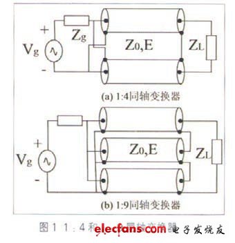
Impedance converters and impedance matching networks have become an essential part of RF circuits and maximum power transmission systems. In order to achieve the best power matching between the input and output of the broadband RF power amplifier, the design of the matching circuit becomes an important task of the RF power amplifier. To achieve maximum power transfer within the wideband, matching circuit design is very difficult. The coaxial converter circuit designed in this paper can achieve high efficiency circuit matching. The coaxial converter has the characteristics of large power capacity, frequency bandwidth and shielding, and is widely used in the VHF/UHF band. Common coaxial converters have 1:4 and 1:9 impedance transformations, as shown in Figure 1. However, in practical applications, when the line impedance does not match the load, their impedance transformation is no longer simply considered as 1:4 or 1:9. This paper proposes a simplified analysis method by establishing a model.
1 coaxial converter model
The coaxial converter has three important parameters: impedance transformation ratio, characteristic impedance and electrical length. The length of electricity used here is for analysis convenience. When the medium and length of the coaxial line are constant, the electrical length is a function of frequency, and the frequency can be ignored.
1.1 ideal model
The input and output impedances of the ideal 1:4 converter are matched. The input and output impedance of each coaxial line is equal to its characteristic impedance Z0. The equivalent model is shown in Figure 2.
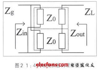
The source impedance Zg and ZL load impedance transformation ratio is:
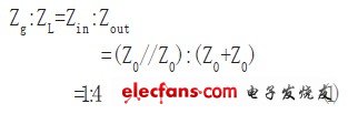
Figure 2 and equation (1) show that the impedance conversion ratio of the converter is equal to the ratio of the input impedance to the output impedance.
The input impedance of the coaxial converter is equal to the input impedance of the coaxial line in parallel, and the output impedance is equal to the output impedance of the coaxial line in series.
1.2 general model
Since the characteristic impedance is a real number, and the source impedance and the load impedance are generally complex numbers, it cannot be simply calculated using the conversion ratio. Impedance matching is the conjugate of the input impedance equal to the source impedance to achieve maximum power transfer. A circuit with a characteristic impedance of Z0 and a lossless coaxial line with an electrical length of E is shown in FIG.
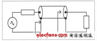
Since the source impedance does not match the coaxial line characteristics, the reflection coefficient of the circuit is not the load reflection coefficient.
Asymmetric Thyristor is the abbreviation of thyristor, also known as Silicon Controlled Rectifier, formerly referred to as thyristor; thyristor is PNPN four-layer semiconductor structure, it has three poles: anode, cathode and control pole; thyristor has silicon rectifier The characteristics of the parts can work under high voltage and high current conditions, and their working processes can be controlled and widely used in electronic circuits such as controlled rectifiers, AC voltage regulators, contactless electronic switches, inverters, and inverters.
Asymmetric Thyristor
Asymmetric Thyristor,60Ma Asymmetric Thyristor,Oem Asymmetric Thyristors,Electronic Component Asymmetric Thyristor
YANGZHOU POSITIONING TECH CO., LTD. , https://www.yzpst.com