
1 Introduction
This article refers to the address: http://
In recent years, with the rapid improvement and rapid development of manufacturing automation, the information tracking management of production lines has become more and more important. The core of product information tracking management is to have a carrier that indicates the information of the product itself. Common information carriers include QR code, barcode, and RFID (Radio Frequency Identification). RFID is a rapid identification technology that has been rapidly developed in recent years. The stored information code is obtained through contactless identification of the code carrier. The code carrier is also known as the electronic tag (TAG). Compared with the traditional bar code technology, the electronic tag has the advantages of large data memory capacity, readable and writable, non-contact identification, high temperature resistance, corrosion resistance and harsh environment, and penetration. Sexually accessible and readable, it can penetrate non-metallic or non-transparent materials such as paper, wood, plastic, etc., and has a low misreading rate, so it is widely used in various industries.
This article introduces the examples of RFID technology used in the automotive industry with the experience of actual project use, and realizes the tracking management of the paint shop body information.
2. Overall structure of the system
2.1 Structure of the body tracking system
Shenlong Automobile Co., Ltd. Wuhan Second Factory paint workshop has reached the benchmark level of PSA global lean model factory from production management to manufacturing process equipment and technology. The internal body tracking system in the workshop adopts the current advanced RFID identification technology. The overall design structure of the system is shown in Figure 1. From the control point of view, it is roughly divided into three levels as shown in the figure: the basic equipment layer, the control layer, and the central management layer; the ERP layer belongs to the enterprise management layer. The body data flow is shown by the arrows in the figure. The data between the levels is transmitted in both directions, and the body information required for production management is permanently stored in the data server. In the production process, the process, robots, and conveying equipment can obtain the body information necessary for the production from the electronic label.
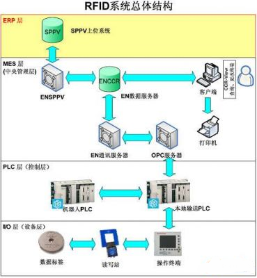
Figure 1 RFID system overall structure
2.2 System components task brief
1) Central management: The EN data server is the data processing management center of the entire system. Responsible for information management and control of production processes, connected to the enterprise ERP system, under the management of the entire paint shop production logistics guidance, information collection. The on-site client, which is part of the central control system, can realize online query and modify the actual body information in the workshop, such as color and model, through the application system CCR-View operating platform.
2) Control layer: The local conveying PLC mainly controls the operation of the conveyor chain, and is responsible for the role of the body information uploading. After receiving the information sent by the central management layer, it is responsible for passing to the lower layer read/write station, and receiving the lower layer read/write. After the information uploaded by the station is transferred to the robot PLC, large-screen display panel and process PLC, the electrophoresis line control PLC can call different voltage parameters when receiving different vehicle type information; the painting robot PLC can be based on the received model and color information. Process control is achieved by selecting different spray paths and paint line paint. This project uses Schneider Premium 57 series 5634M CPU, using Ethernet connection for information transfer.
3) Basic equipment layer: mainly includes complete RFID (Radio Frequency Identification System) and field operation terminal. The RFID system consists of an electronic tag (Tag) and a read/write station. The electronic tag is used to store the necessary bodywork information. The read/write station reads and writes data from the tag. The read/write station communication protocol is based on TCP/IP. Directly through the Ethernet and control PLC connection; the field operation terminal is used to control the reading and writing station, providing a human-computer interaction interface, which can display the relevant information stored in the electronic tag, and can realize local information input and modification under emergency or information error conditions. , query and other functions.
3. System function
3.1 Information transmission methods and characteristics before using RFID
Before using RFID technology, the storage body information is mainly paper barcode. The barcode method is to set the client of the SPPV system of the enterprise management layer at the function demand point. By reading the barcode, query the database of the SPPV system to obtain the required body. Information to guide production management. The advantage is convenient and flexible. The disadvantage is that it has great limitations for the production management of the workshop. It can only provide information such as models and colors, and cannot be integrated into the control of the workshop automation system. With the development of optoelectronic technology, for a period of time, many auto companies have also used a bar code extension technology - mechanical bar code (mechanical comb), which is to install a unique steel bar code on each sled, using photoelectric sensors To scan and read and write to complete the transmission of different body information, the characteristics of the body information must be stored in the PLC, set a special body data PLC to manage all the body data running inside the workshop, BODY DATA PLC has a lot of data exchange in the workshop operation, Therefore, high performance requirements for PLC, large-capacity memory, and high speed and reliability requirements for network communication.
3.2 RFID solution
After adopting the RFID system, an electronic tag is installed in the protection box of each ski bottom. The electronic tag stores a large amount of information such as bar code, model, color, vehicle definition code, etc., and forms a plurality of small mobile databases, which are read throughout the production process. The write site is readable and writable. After the multi-party technology research and program demonstration, the second project paint project of Wuhan selected the RFID identification system of EMS company. The electronic tag uses the HMS150HT high temperature series up to 240 °C, and the mobile electronic tag stores a lot of body and logistics guidance information (see Figure 2).
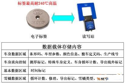
Figure 2 mobile electronic label
Therefore, when the local PLC communicates with the data server abnormally, the information stored by the RFID system using the electronic tag can still be produced without causing the termination of large-scale production. The read/write head adopts HF-CNTL-IND-02, and the communication protocol is based on TCP/IP, which has faster transmission speed and better stability. According to the production and management functions, a total of 26 sets of read/write stations are set up at the entrance of the paint shop, the branching of the workpiece stream, and the important process (such as electrophoresis line, UBS line, spray booth, storage area, etc.). In order to realize RFID tracking management and control of the whole production process of the vehicle body entering the paint shop to the hair assembly.
3.3 Main functions of the body tracking system
3.3.1 Production Management Guidance Function
1) Body data guides robots and manually identify models, spray colors,
2) Management of various body logistics: including the introduction, export, side thickness management, multiple cycle statistics, etc.
3) Management of the vehicle: including bottom, paint sled, UBS spreader cleaning, export repair, etc.
4) Transfer body information to the downstream workshop system.
3.3.2 Information Statistics Report Function
1) Real-time statistics of the number of products in each process segment and production line area,
2) Statistical reports on production information such as classes, days and months,
3) The number of various types of vehicles that have been produced by model and color statistics
3.3.3 Real-time monitoring function of the production line
1) Find the specific location of a car, such as in the storage area or point repair room, etc.
2) Check the status of the online or historical body in the paint shop,
The RFID body tracking system is an important sub-module of the paint shop ENCCR system. All relevant production management personnel can log in through the independent use authority. From the central control room or the on-site client CCR-View platform, the RFID body tracking system can be accessed to realize the production information. Real-time query and print function.
4. Software design
4.1 Read and write station standard function block internal structure
In terms of software, Wonderware's InTouch 9.0, which is used in the paint shop monitoring system of the second factory, is used as the host computer configuration software. The read/write station uses the standard Ethernet protocol to connect and communicate with the operating terminal and PLC. The communication program between the PLC and the read/write station controller is the read/write station function block MFC_MAIN and MFC_MAIN function block of the Premium PLC developed by Unity Pro. Covers all necessary program logic related to the read/write station. The block structure is shown in Figure 3:
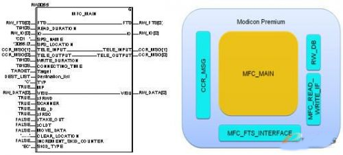
Figure 3 block structure
The internal structure of the main program block mainly includes a message message CCR_MSG with the central monitoring system, an interface MFC_FTS_IF with the delivery system, an interface MFC_READ_WRITE_IF with the read/write system, and a data interface RW_DB with the operation terminal.
4.2 Timing logic of standard blocks
The standard read/write station program logic is shown in Fig. 4. In the figure, the solid line No. 1 and the dotted line No. 2 are the exchange signals between the transmission system and the reading and writing station in the program, which mainly include the cyclic start FT_START signal sent to the reading and writing station. The cycle end signal SDS_FINISHED, and the feedback signal SDS_DFRG sent by the reader station to the conveyor system and the modification and confirmation signal FT_DFRG of the conveyor system; the solid line command 5 is the execution signal READ and WRITE of the read/write system; Refers to the message signals REQ_D and DATA_D of the PLC and CCR logistics tracking system database. The dotted line No. 4 is the message response signal DATA_P of the CCR database to the PLC; the dotted line part of the DATR and DATW signals is the data status after the read and write commands are executed. That is, the data packet read or written.
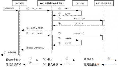
Figure 4 standard read and write station program logic
4.3 PLC package format
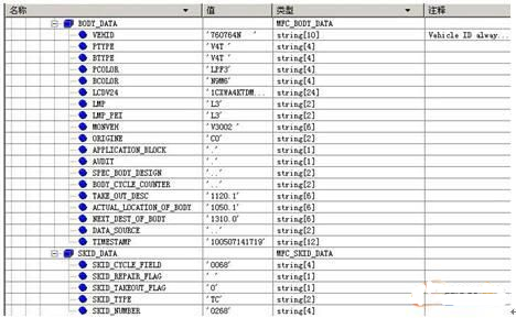
Figure 5 site extracts data
As mentioned above, the electronic tag contains four types of data. In most cases, the read/write station function block does not need to read all the data in the tag, or the physical location of the read/write station determines the reading and writing station. The read range of the data interface is different, which can effectively shorten the read byte length, thereby saving read/write time. For most sites, only key data such as body and sled are extracted during operation. As shown in Figure 5 below, these data are subordinate to the RW_DB block. RW_DB acts as the interface between the PLC and the operation terminal. In addition to the data information, it also defines the operation process. Status, error messages, and emergency handling, including manual input of body bar codes, sleigh numbers, etc.
5. System reliability
All technical solutions used in industrial systems, stability and reliability are the first determining factors, leaving none of them to reflect the practical value of industrial applications. Looking at all aspects of the overall structure of the RFID identification system, the main factors affecting stability and reliability are:
5.1 Reliability of data sources
Referring to the data source, for the system, the data source includes three methods: label source data, manual operation of the operation terminal,
The central control room database is manually edited. In the automatic operation mode of the system, at the entrance of the workshop, the RFID reading and writing system will write the source data in the database into the electronic tag, and bind it to the sled in the system. When the positioning of the conveying system is accurate, the test vehicle is removed. Test vehicle, the reliability of the first point of writing has been as high as one thousandth. The other two data entry methods are mainly in the case of emergency situations, such as commissioning vehicles without body information, test vehicles passing through the paint shop, manual entry of body information, or manual introduction of vehicles without body information, which needs to be defined in the database. Information. The process of manual intervention brings risks to the reliability of the data source. Therefore, detailed operation procedures and instructions are pasted on the operation terminals of all read/write stations to minimize the risk and ensure the reliability of the system.
5.2 Reliability and stability of data transmission
From the perspective of the structure of the RFID system, the two-way transmission of the body data from the electronic tag to the central control room database has to go through four links: read/write station, operation terminal, transport PLC, data server, in which the read/write station uses radio waves, which is reliable. The recognition rate is up to 99.99%. The data transmission of the other three links adopts 10M/100M industrial Ethernet. The transmission speed and communication distance are reliable, and the devices in the lower three layers are local, and the distance between Ethernet connections is also Not long, even if there is a problem with the communication with the central control room database, the local device can still be downgraded, without affecting the transmission of the underlying data and the operation of the device.
6. Conclusion
Since the mass production of the second plant of Wuhan Second Automobile Co., Ltd. since June 2009, the body tracking system has been running stably, the RFID system has reliable reading and writing information, and the misreading rate is low. The selected electronic tags are in high temperature, acid and alkali and other harsh environments. It runs well, the operating system has a friendly man-machine interface and is easy to operate. The body tracking system greatly enhances the guidance and management functions of the whole workshop production process and effectively improves production efficiency. The successful example of RFID technology applied in the paint shop of Wuhan No. 2 Factory of Shenlong Automobile Co., Ltd. has certain positive significance for promoting the promotion of RFID full paint shop solution in PSA Group.
The output current programmable constant power led driver is the most high-profile solution for Flood Light LED Driver from 42W to320W. It`s compatible with various safety regulations, certified with UL, CE, TUV, ENEC, CB, SAA, BIS, KC, etc, integrating the function of output current adjustable with 3-in-1 dimming, for customers to choose the output current demand and 1-10Vdc, PWM signal and timer control by just one single driver.

The output current adjustable led driver is a perfect power proposal for led Flood light, the flood light led driver power from 26W to 150W. It does satisfy the demands for both function and cost effective together, certified by CE institute. The compact metal case and high efficiency enables the driver to operating with high reliability, and extending product lifetime to at least 50,000 hours.

The economic output current fixed led control gear is focused on quality reliable and cost decreased at the same time to offer the best economic flood light led driver solution for light from 26W to 150W. Approved by CE institute, the led driver with multiple protections, like output OVP, SCP and OTP ,surge protection up to 6KV and wild range working temperature to ensuring the lifetime also at least 50,000 hours.
MOSO flood light led driver with it`s wild range options, satisfied all the customers` requirements from the whole world.
Flood Light LED Driver
Flood Light LED Driver,Programmable Flood Light LED Driver,Dimmable Flood Light LED Driver,Dali Flood Light LED Driver
Moso Electronics , https://www.mosoleddriver.com