
introduction
This article refers to the address: http://
In recent years, people have been paying attention to and researching the driving safety of cars on mountain roads. As a new active safety system, the early warning system will further increase the safety of automobiles, reduce the incidence of accidents, and continuously meet the growing market. According to a survey by Daimler Benz, an alarm of 0.5 seconds in advance can prevent a 60% rear-end collision, and 90% can be prevented by 1.5 seconds in advance. Therefore, the automobile road safety warning system can help the driver to correctly and reasonably operate the car when driving in the mountainous area, and reduce the probability of traffic accidents, which is of great significance for ensuring safe driving of mountain roads.
Overall design of early warning system
Based on the driving safety model of the car-coupled car in the mountainous area, the system takes the automobile mountain road driving safety early warning system as the research object, realizes signal acquisition, conditioning and transmission, and finally achieves the purpose of early warning. In order to realize the real-time warning of the vehicle, it is necessary to collect the parameters such as the operating conditions of the vehicle, the road running condition and the surrounding environmental conditions in real time, determine the running state according to the corresponding data collected, and then use the processor to perform the early warning algorithm. Make corresponding voice prompts to ensure that the driver drives safely and achieve the purpose of reducing traffic accidents.
Through the study of the purpose of the system, the hardware circuit of the early warning system can be roughly divided into three parts: input module (signal determined according to the security model, sensor acquisition), digital signal processor (DSP) module and output module (voice) Alarm prompt module). The processor is the core, and the signal input and output are connected through a bus and an interface circuit. These modules form the overall block diagram of the road safety warning system for mountain road vehicles, as shown in Figure 1.

Figure 1 system composition block diagram
The input module of the early warning system includes the acquisition of signals and processing of the acquired signals. The signals that need to be collected in this system include vehicle running status signals (such as vehicle travel speed, etc.), road parameters (such as slope, etc.) and surrounding environmental conditions (such as temperature). The difference between these signals is different from the adjustment circuit of the sensor and sensor to be selected. The acquisition and processing circuit design of the vehicle speed signal will be briefly introduced later.
Digital signal processors (DSPs) are widely used due to their high performance and flexible programming advantages. Various companies have a wide variety of DSP chips for different applications. Therefore, when designing DSP systems, it involves reasonable DSP chips. Choose the problem. The TMS320 series DSP produced by TI is currently the most influential mainstream DSP product in the world. The chip is characterized by low price, easy to use and powerful functions. This system selects the TMS320LF2407A DSP chip, which is the world's most integrated and powerful motion control DSP chip, which lays a good foundation for extending its control function after successful warning.
The output module of the early warning system is mainly a voice prompt module. A voice prompt signal is issued a period of time before the danger may occur, early warning of the driver to correctly operate the car, and active protective measures to reduce the occurrence of traffic accidents.
Early warning system hardware design
The driving safety model of mountain roads mainly analyzes the driving conditions of large downhills, uphills and curved roads in mountainous roads. There are many signals to be collected, and the input signal circuit is also different. The following briefly introduces the driving speed of the vehicle. Signal acquisition and processing circuit design.
Adjustment circuit design of speed sensor
The car travel speed measurement uses a Hall switch sensor. In this paper, the Hall sensor with model 2SS52M is selected. According to its main technical parameters, the 2SS52M Hall sensor is a voltage sensor with an output voltage range of 0~3.3V, which does not exceed the DSP A/D conversion voltage. However, in practical applications, since the Hall sensor is usually mounted on the rotor shaft of the motor, it is inevitably subjected to strong electromagnetic interference. In order to improve the anti-interference performance of the system, the signal it sends needs to be processed by high-speed optical isolation. In addition, in order to make the quadrature coded pulse transmitted by the Hall speed sensor is a standard sinusoidal waveform, the signal is shaped by the 74LVC14A chip, and the shaped waveform is input to the QEP pin of the DSP. The circuit connection is shown in Figure 2. Since the 74LVC14A chip is a six-inverted Schmitt trigger, it can transform a non-rectangular wave into a rectangular wave. The shaping principle is shown in Figure 3.
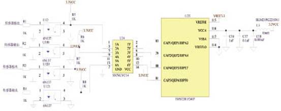
Figure 2 Hall sensor adjustment circuit

Figure 3 Pulse shaping with a Schmitt trigger
Hardware design of voice prompt module
The voice prompt is implemented by the voice chip ISD1730 driver speaker.
When the car is running on the mountain road, the input signal is collected by the input module, and the controller module comprehensively calculates and judges the safety degree. If it is not safe, the DSP (TMS320LF2407A) module outputs the control voice module, and the voice chip outputs the audio. The signal is output through the power amplifier circuit to realize the early warning function. The DSP (TMS320LF2407A) integrates the SPI interface to facilitate serial communication with the ISD1730. The interface circuit of the TMS320LF2407A and the voice chip is shown in Figure 4.

Figure 4 Interface circuit of TMS320LF2407A and voice chip
As can be seen from Figure 4, the DSP and the voice chip ISD1730 are connected by four wires. The SPISTE pin of the DSP is connected to the chip select signal SS of the ISD1730. This pin controls whether the ISD1730 voice chip is strobed, and the DSP SPISIMO tube. The pin is connected to the serial data input terminal MOSI of the ISD1730. This pin provides the control command word and playback address for the voice chip. The SPIMISO pin of the DSP is connected to the serial data output terminal MISO of the ISD1730. The DSP receives the voice chip from the pin. The returned signal, the SPICLK pin of the DSP is connected to the serial clock input terminal SCLK of the ISD1730. This pin provides the clock signal for the voice chip ISD1730. The Ros of the ISD1760 is connected to the 80K resistor to the ground, and the sampling frequency is set to 8KHz. The recording time is 60s; before the system realizes the warning, you can use the recording software to record the desired .wav format audio source file, then input the audio file into the computer's CoolEdit or Goidwave software for editing, and then pass the desired content through the ISD1700S. The voice programming copy machine is segmentally recorded into the voice chip (the SPI mode performs copying of the multi-chip voice information.
System software design
Only a combination of software and hardware can better complete the warning function. The hardware circuit of the system has been designed in the foregoing. The software part of the warning system function is introduced below.
In the software design process of TMS320LF2407A, the hardware-related registers are set by assembly instructions, the I/O input and output programs are written, and the driving safety warning algorithm program is written in C language. The structure of TMS320LF2407A vehicle mountain driving safety warning software is shown in Figure 5. The software design of this system is divided into four modules: main control module, A/D conversion module, I/O module and early warning module. The master program module controls the operation of the entire software. The A/D module converts the analog signal collected by the sensor into a digital signal; the I/O module controls the TMS320LF2407A and external data input and output; the warning module obtains the driving safety level value and the voice prompt signal. The following mainly introduces the next warning process.
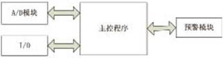
Figure 5: Early warning system software structure
Early warning process
The early warning system is a voice alarm when the car is about to be unsafe when driving on a mountain road. The software structure mainly includes three parts: the system initialization subroutine, the SPI initialization program and the interrupt service subroutine. The main program is responsible for judging whether it is necessary to broadcast the voice information, and finding the storage address of the voice information, and the interrupt service subroutine is responsible for placing the received address. Save it in the APC register of the voice chip. The process of achieving early warning is as follows.
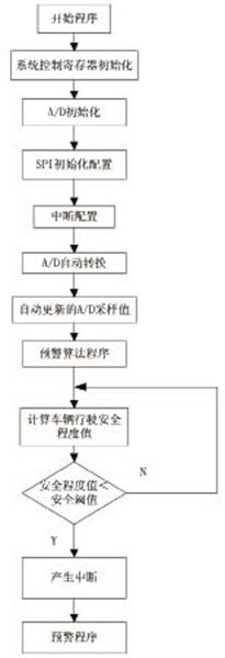
Figure 6 early warning flow chart
The DSP (TMS320LF2407A) A/D interface digitizes the collected information, and then obtains the vehicle driving safety level value through the early warning algorithm program, and provides an early warning signal to the voice chip ISD1730. The early warning process is shown in Figure 6 (see next page). After the program starts running, first initialize the DSP control register SCSR, then initialize the A/D control registers ADCTRL, MAXCONV, CHSELSEQ, then set the SPI port parameters, and then configure the interrupt IMR, IFR. After this, the A/D automatic conversion starts running, and the vehicle operating conditions, road parameters and surrounding environmental conditions obtained by A/D sampling are calculated by the mountain road vehicle driving safety warning algorithm to calculate the safety level of the vehicle at that time. Then, the security thresholds in the model are compared and judged, and different procedures are executed according to the degree of security of the warning. When the security level is low, the DSP executes an alert subroutine to perform a voice broadcast warning.
Conclusion
Through the soft and hardware design of the road safety warning system for mountain roads, the vehicle must finally drive safely on the mountain roads, remind the driver in the first few seconds of the danger, and understand the current operating state, so as to better Make corresponding remedies. This has great practical significance for reducing road traffic accidents in mountainous areas and safeguarding people's property and personal safety.
N-net 24 Ports Poe Switch series includes the fast Ethernet series and gigabit series, also the managed and unmanaged series. It supports 24 ports PoE ports with up to 30W PoE output per port and total power budget 440W(Built-in power supply). PoE is especially suitable for devices that are far from power outlets or when users want to minimize the clutter of extra cables as power is supplied via the Ethernet cables themselves.
This series enables users to easily connect and supply power to PoE-capable devices such as wireless Access Points (APs), IP cameras, and IP phones. It can also connect other Ethernet devices like computers, printers, and Network Attached Storage (NAS) to fit into any type of network application.
4 Combo uplink ports means businesses can increase their network bandwidth via wired speed while offering redundancy so voice and surveillance data are transferred reliably. The combo design can increase bandwidth by offering two Gigabit copper or fiber connections, giving administrators more options for expansion.
Poe Switch 24 Ports,24 Ports Poe Switch,Managed 24 Ports Poe Switch,Poe Switch For Ip Camera, 10/100M 24 Ports POE Switch, Unmanaged 24 Ports POE Switch
Shenzhen N-net Technology Co.,Ltd , http://www.nnetswitch.com