
Introduction
In switching power supplies, EMI filters play a crucial role in suppressing both common-mode and differential-mode conducted noise. This paper explores a method for independently analyzing and modeling these two types of signals, leading to the development of a structured design procedure for EMI filters.
High-frequency switching power supplies are widely used across various industries, including industrial, defense, and consumer electronics, due to their compact size, high power density, and efficiency. However, when connected to the AC grid, the rectifier circuit often causes input current to be discontinuous, which not only lowers the power factor but also introduces significant harmonic distortion. Additionally, the fast switching action of power devices (ranging from tens of kHz to several MHz) generates electromagnetic interference (EMI), making it a critical concern in power supply design.
To mitigate conducted interference, engineers employ strategies such as proper grounding, star-shaped layouts, minimizing common impedance, designing effective snubber circuits, and reducing stray capacitance. Another effective approach is the use of EMI filters to suppress noise between the power grid and the switching power supply.
EMI disturbances are typically complex and challenging to model precisely. Therefore, filter design often involves an iterative process, refining parameters until the desired performance is achieved. This paper presents a practical method for EMI filter design by analyzing the common-mode and differential-mode noise models separately, providing a step-by-step example for real-world implementation.
1. EMI Filter Design Principles
The main source of EMI in switching power supplies is the rapid voltage and current changes caused by the switching of power semiconductor devices. These result in broadband noise that spans from the switching frequency up to several MHz. According to international standards, conducted EMI measurements are typically taken between 0.15 MHz and 30 MHz. Hence, the goal of EMI filter design is to provide sufficient attenuation to the switching frequency and its harmonics, ideally reducing EME above 150 kHz to acceptable levels.
The concept of a low-pass filter, well-established in digital signal processing, is equally applicable in power electronics. A successful EMI filter must meet the following criteria:
1) Sufficient stopband attenuation at the required frequency;
2) Minimal loss at the grid frequency (passband);
3) Cost-effective design.
1.1 Common Low-Pass Filter Models
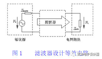
EMI filters are usually placed at the input of the power supply connected to the grid, forming a low-pass filter using a series inductor and shunt capacitor. The filter’s performance depends on the input and output impedances. Different filter orders (first, second, or third) can be used to achieve the desired attenuation. At high frequencies, the transfer function is often approximated by ignoring higher-order terms. Table 1 shows common filter topologies and their corresponding transfer functions. It is important to consider the impact of impedance mismatch on filter performance.

1.2 EMI Filter Equivalent Circuit
Conducted EMI consists of two components: common-mode (CM) and differential-mode (DM) noise. CM noise occurs between the AC lines and ground, while DM noise exists between the live and neutral lines. Due to different sources and paths, separate filtering is necessary for each mode.
To effectively suppress noise, it is essential to measure and analyze each mode individually. This helps determine the specific noise level and optimize the filter design accordingly. For example, in a standard filter topology, the common-mode and differential-mode components have distinct roles. The common-mode choke suppresses CM noise, while the differential-mode capacitors handle DM noise. However, parasitic effects can influence both modes, requiring careful consideration during design.
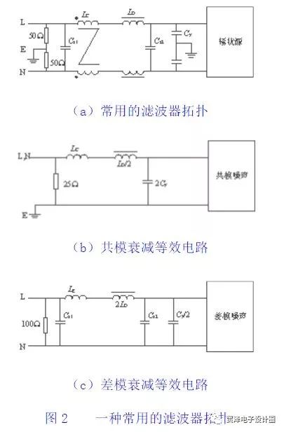
From the analysis, the common-mode filter behaves as a second-order LC low-pass filter, with equivalent inductance LCM and capacitance CCM. Meanwhile, the differential-mode filter acts as a third-order CLC low-pass filter, with LDM and CDM. Calculations show how these values affect the cutoff frequency and overall performance.
2. Practical EMI Filter Design Method
2.1 Key Considerations in Design
The effectiveness of an EMI filter depends not only on its own components but also on the noise source and grid impedances. The grid impedance is typically measured using a LISN (Line Impedance Stabilization Network), which includes inductors, capacitors, and a 50 Ω resistor to simulate standard conditions. The source impedance varies depending on the converter topology and layout.
For instance, in a flyback converter, the source impedance alternates between a voltage and current source based on the rectifier bridge’s operation. This dynamic behavior requires careful measurement and modeling to ensure accurate filter design. Real-world components also introduce parasitic effects, making high-frequency modeling complex. As a result, many designs focus on low-frequency suppression.
2.2 Step-by-Step Design Process
Designing an EMI filter involves balancing size, cost, and performance. Before starting, it is essential to measure the source and grid impedances and the noise spectrum. Using a noise separator, common-mode and differential-mode noise levels can be identified. Based on these measurements, the required attenuation levels are calculated.
Next, the intersection points of the noise spectra with the desired attenuation curves are determined. These points help define the cutoff frequencies for the filter. Component selection follows, with considerations for leakage current and component tolerances. For example, the value of Cy must be chosen carefully to limit ground leakage current while meeting safety standards.
3. Conclusion
This paper discusses the design of EMI filters based on low-frequency models. However, actual performance may require adjustments due to parasitic effects and high-frequency behavior. Multi-stage filters are often needed for higher attenuation levels. Moreover, the design process is highly dependent on the specific application, making general-purpose filters difficult to implement without customization. Therefore, real-world design often involves iterative testing and optimization to meet technical requirements.
Core Drill Sand Blasting Machine,Automatic Diamond Sandblasting Machine,Saw Blade Sand Blasting Machine,Diamond Saw Blade Sand Blasting Machine
Suzhou Mountain Industrial Control Equipment Co., Ltd , https://www.szmountain.com