
"Control Loop Design for Linear and Switching Power Supplies" is the latest book by Christophe Basso, a former columnist at Power Electronics. This publication provides essential knowledge that engineers must master to properly compensate and stabilize a control system. It includes an excerpt from the book discussing stability standards.
In the field of electronics, an oscillator is a circuit that generates a self-sustained sinusoidal signal. In various configurations, the start-up process of an oscillator involves noise inherent in the electronic components. Upon power-on, the noise level increases, triggering oscillation and self-excitation. Such a circuit can be composed of modules as shown in the figure. As you can see, this configuration closely resembles that of a control system.
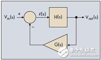
Figure 1: The oscillator essentially functions as an error signal that does not interfere with the output control system.
In our example, instead of noise, the excitation input is the voltage Vin, which acts as an input variable to initiate the oscillator. The direct path consists of the transfer function H(s), while the feedback path contains the G(s) block. To analyze the system, we first write its transfer function based on the relationship between the output voltage and the input variable:
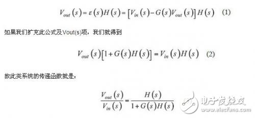
In this equation, the product G(s)H(s) is known as the loop gain, denoted as T(s). For the system to become a self-excited oscillator, it must produce an output even when the input disappears. This requires the following conditions to be met:
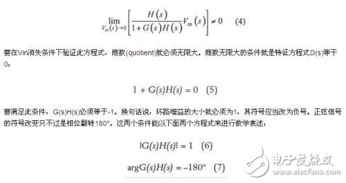
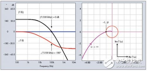
Figure 2: Oscillation conditions can be represented using Bode plots or Nyquist plots.
When these two equations are satisfied, the system reaches steady-state oscillation, known as the Barkhausen criterion, proposed by German physicist Barkhausen in 1921. In a control loop, this means the correction signal no longer opposes the output but returns in phase with the same amplitude as the excitation signal. Equations (6) and (7) represent the loop gain curve on a Bode plot, crossing the 0 dB axis with a 180° phase lag. On a Nyquist plot, the relationship between the imaginary and real parts of the loop gain is plotted, intersecting at -1, j0. Figure 2 shows two curves that satisfy the oscillation conditions. If the system slightly deviates from these values (e.g., due to temperature drift or gain variation), the oscillation will either decay exponentially or grow until limited by the power rails. In oscillator design, the goal is to minimize the gain margin so that oscillation conditions are met under various operating conditions.
**Stable Condition**
As you know, the goal of a control system is not to create an oscillator. We want the system to respond quickly, accurately, and without oscillation. Therefore, we must avoid configurations that lead to oscillation or instability. One approach is to limit the frequency range in which the system reacts. By definition, the bandwidth corresponds to the frequency where the closed-loop gain drops by 3 dB. The bandwidth represents the range of frequencies where the system performs well, tracking setpoints or suppressing disturbances effectively. During the design phase, we don't directly control the closed-loop bandwidth, but rather the crossover frequency fc, which is related to open-loop analysis. While these two parameters are often considered similar, they are not always equal, though they are close enough for practical discussions.
We have seen that the open-loop gain is a critical parameter in the system. When |T(s)| > 1, the system operates in a dynamic closed-loop mode, compensating for disturbances or responding to setpoint changes. However, there are limits to how fast the system can react. It must provide sufficient gain at the frequency of the disturbance. If the setpoint change occurs too quickly, the frequency component of the signal may fall below the system's bandwidth, leading to a lack of gain and a delayed response. The system behaves like a non-responsive loop, unable to track waveform changes. So, is infinite bandwidth desirable? No, because increasing bandwidth is like widening a funnel—it allows more information and faster response, but also captures more noise and parasitic signals, such as switching ripple in power supplies. Thus, it’s essential to limit bandwidth to what the application truly needs. An overly wide bandwidth can reduce the system’s ability to reject noise and external interference, compromising overall robustness.
4.3-10 Connector,Mini Din To N Connector,4.3-10 To N Connector,4.3-10 Mini Din To N Conenctor
Changzhou Kingsun New Energy Technology Co., Ltd. , https://www.aioconn.com