
The fundamental principle and key features of the seven-electrode conductivity sensor are explained in detail. Based on the physical properties of the sensor and the need for high-precision measurements, a measuring circuit was designed that offers low temperature drift, high accuracy, and fast response. This circuit utilizes integrated components such as D/A and A/D converters to ensure precise drive signals and high-speed sampling. Compared to traditional methods, this approach provides more accurate frequency and voltage control, making it easier to adjust. Additionally, high-speed sampling helps avoid signal distortion during the conditioning process. Experimental results confirm the effectiveness of the circuit.
Conductivity measurement plays a crucial role in various fields, including industrial production, environmental monitoring, and marine resource exploration. Accurate and rapid conductivity measurement is essential for marine research and environmental protection. Conductivity sensors can be broadly categorized into electrode-based and electromagnetic types. The electromagnetic type operates based on electromagnetic induction, where changes in conductivity are reflected through variations in induced electromotive force. In contrast, electrode-based sensors rely on electrolytic conduction, with changes in solution conductivity reflected by resistance variations. Due to their fast response and high precision, electrode-type sensors have gained significant attention. This article explores the working principle of the seven-electrode conductivity sensor and outlines the design of its measurement circuit.
**Working Principle and Overview**
The seven-electrode conductivity sensor is a highly precise type of electrode-based sensor, combining the advantages of three-electrode and four-electrode configurations. Its conductivity cell separates the "current" and "voltage" electrodes, reducing polarization resistance and allowing for a larger flow channel and faster response time, enabling quick conductivity measurements. Additionally, two grounding electrodes at both ends of the cell help shield external interference, ensuring that the measurement remains unaffected by surrounding factors. This design also eliminates the need for a pump during measurement, further enhancing accuracy.
**1.1 Principle Analysis of the Seven-Electrode Conductivity Sensor**
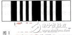
Figure 1 shows the schematic diagram of the seven-electrode conductivity sensor, which consists of seven platinum rings embedded in quartz glass. Electrodes 1–4 and 4–7 form two sets of measurement units, with current flowing through the common electrode 4. When current flows between the ground electrode 1 and electrode 7, currents pass through electrodes 2, 3, and 5, 6. By applying a constant voltage between electrode 4 and ground, changes in current through the common electrode reflect changes in resistance, allowing the conductivity of the solution to be calculated.
**1.2 Overview of the Measurement System**
To achieve high-precision measurement using the seven-electrode conductivity sensor, several design considerations were made: (1) minimizing the use of analog components to reduce noise, and instead relying on high-speed sampling to extract signal information. (2) Using the same reference for both A/D and D/A conversion ensures that the ratio of driving voltage to sampling resistor voltage remains consistent, even if the reference fluctuates slightly. (3) All system components, especially the operational amplifiers and sampling resistors used to drive the seven electrodes, are selected for low temperature drift and high precision.
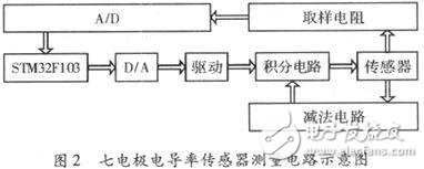
Figure 2 illustrates the schematic of the measurement circuit system. The STM32F103 microcontroller controls the D/A converter to generate a fixed-frequency and fixed-voltage signal. The sensor is driven by a constant voltage source formed by an integrated circuit and a subtraction circuit. The current passing through the sampling resistor generates a voltage that reflects the conductivity value. This voltage is then converted to digital form via A/D conversion and processed by an algorithm to determine the final conductivity reading.
The system uses the STM32F103 microcontroller, part of the STM32 series, which is a 32-bit ARM core-based microcontroller with medium capacity. It features 64 or 128 KB of flash memory and includes USB, CAN, 7 timers, 2 ADCs, and 9 communication interfaces. This makes it ideal for use in industrial control systems, measurement devices, and other applications requiring reliable and precise performance.
Heat-shrinkable Tubing For Cable Outer Protection
Heat-shrinkable tubing for cable outer protection
Heat-shrinkable tubing for cable outer protection,Heat-shrink tube,Heat shrinkable tubing,thermal contraction pipe,Shrink tube
Mianyang Dongyao New Material Co. , https://www.mydyxc.com