
1. Introduction
In many testing systems, real-time data acquisition is essential while the system is in motion. If the test process is not continuous or if the testing location and data acquisition point are separated, synchronization issues can arise, leading to inaccuracies. To ensure precise measurements, it’s crucial that motion control and data acquisition work in sync. National Instruments offers PCI bus E-series data acquisition and motion control cards that integrate with the RTSI (Real-Time System Integration) bus, enabling accurate synchronization and real-time processing. This article explores how to use RTSI bus programming to achieve seamless synchronization between motion control and data acquisition.
2. What is the RTSI Bus?
The RTSI bus is a high-speed digital interface designed for real-time integration between National Instruments devices. It supports fast communication between data acquisition, image capture, and motion control modules. With seven trigger lines, it allows flexible synchronization across various instruments. These signals can be routed via software, enabling one signal to trigger multiple devices. Common applications include triggering image capture, data acquisition based on motion events, and capturing position data from external triggers.
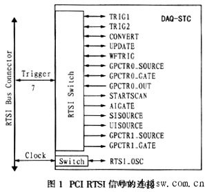
For the E-series data acquisition card, 15 types of signals connect to the RTSI bus, such as time base signals, data acquisition clocks, D/A output clocks, and external PFI signals. Figure 1 illustrates these connections.
3. Synchronization Between Motion Control and Data Acquisition
There are two main methods for synchronization: interrupt-based and capture-based. In interrupt mode, the motion control card moves the motor to a specific position, and the data acquisition card collects data in real-time. In capture mode, the data acquisition card waits for a signal at a certain position and records the current motor position. This article focuses on interrupt synchronization.
3.1 Interrupt Modes
Interrupts can be absolute, relative, or periodic. Absolute interrupts occur when the motor reaches a specific position. Relative interrupts trigger when the motor's position meets a set condition relative to a reference. Periodic interrupts happen at regular intervals. Choosing the right mode depends on the specific needs of the test system.
3.2 How Synchronization Works
When the motor reaches a set position, the encoder sends a signal that generates an interrupt. This signal acts as a trigger for the data acquisition card, allowing it to collect data at the exact moment. Through the RTSI bus, the motion control card sends the interrupt signal to the data acquisition card, ensuring both systems operate in sync. The data acquisition card uses this signal as a clock for sampling, collecting sensor data and storing it in a buffer. Once full, the data is displayed in real-time using multi-threading.
4. Programming Implementation
The synchronization process is illustrated in Figure 2. Using LabWindows/CVI, the author programmed the RTSI bus, data acquisition, and motion control. The NI-DAQ and NI-Motion libraries were used to handle hardware interactions. MAX (Measurement & Automation Explorer) allowed device configuration, assigning unique IDs for programming. Key functions included:
(1) Connecting interrupt signals to the RTSI bus.
(2) Setting motion parameters like velocity, acceleration, and S-curve time.
(3) Configuring interrupt generation positions and enabling interrupts.
(4) Starting motor movement.
(5) Checking motion status and communication status.
5. Conclusion
The RTSI bus provides a reliable, high-speed solution for synchronization in measurement and control systems. By implementing RTSI-based synchronization through LabWindows/CVI, real-time data collection during motion becomes more accurate and efficient. This approach is ideal for applications requiring precise timing and coordination between motion and data acquisition.
vaping, bang vape,vape 30000, vape germany
Niimoo Innovative (HK) CO., LIMITED , https://www.niimootech.com