
1 Ultrasonic Ranging Principle Ultrasonic sensors are devices that convert other forms of energy into ultrasonic energy of the desired frequency or other forms of energy that convert ultrasonic energy into the same frequency. The principle of ultrasonic ranging is to use the single-chip microcomputer to start the counting of the T0 counter of the single-chip microcomputer while the ultrasonic sensor transmits the ultrasonic wave. When the echo signal is detected, the T0 counter of the single-chip microcomputer stops counting. The measured time and the speed of sound are multiplied to obtain the distance traveled during the ultrasonic round trip, so the measured distance S is half of the acoustic wave transmission distance:
This article refers to the address: http://
S=Ct/2
Where: S is the distance between the ultrasonic emission point and the obstacle to be measured; C is the transmission rate of the sound wave in the medium; t is the time interval from the ultrasonic wave to the ultrasonic wave return. The transmission rate of sound waves in the air is: ![]()
Where: T is the absolute temperature; C0 = 331.45 m/s.
Using the method of single-chip pulse counting, the value of t can be accurately measured. Assuming that the machine cycle of the MCU is T machine, then there is t=NT machine, then the measured distance is:
![]()
2 system hardware circuit design
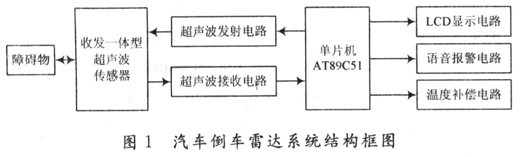
2.1 System Structure The system block diagram is shown in Figure 1. The system consists of a single-chip control circuit, an ultrasonic transmitting and receiving circuit, a temperature compensation circuit, an LCD display circuit, and a voice alarm circuit. The single chip AT89C51 is the core component of the whole system, coordinating the work of each part of the circuit. The single-chip microcomputer starts timing while the ultrasonic signal is emitted. The ultrasonic signal is reflected in the air and encounters an obstacle. The reflected echo signal is processed and input to the INTO terminal of the single-chip microcomputer to generate an interrupt, and the counter stops counting. The number of pulses measured by the counter can be used to obtain the time required for the ultrasonic signal to go back and forth, thereby achieving the purpose of ranging. Ultrasonic probe adopts TCF40-25TR1 type transceiver integrated ultrasonic sensor with resonant frequency of 40 kHz; ultrasonic transmitting and receiving circuit adopts LM1812 professional integrated circuit, which not only has fewer external components, simple circuit, but also has better stability and reliability; The temperature compensation circuit adopts the one-line digital temperature sensor DS18B20, which uses the relationship between the speed of sound and the temperature to correct the sound speed, thereby eliminating the influence of temperature on the speed of sound; the voice alarm circuit adopts ISD4004, which can realize the voice alarm during the reverse operation of the car.
2.2 The core of the control part of the MCU control circuit system is the AT89C51 produced by ATMEL. The AT89C51 is available in a 40-pin dual in-line package (DIP) with internal CPU, 4 KB ROM, 256 B RAM, two 16-bit timer/counters T0 and T1, and four 8-bit I/. The O port is composed of a part such as a full duplex serial communication port. AT89C51 single-chip microcomputer has the characteristics of simple system structure, low cost, high reliability and low power consumption. In particular, the internal integration of 4 KB of FLASH program memory makes the structure of the MCU system simpler and makes it widely used. At the same time, it also features high-level language programming, rich instructions, and simple software development. The AT89C51 single-chip microcomputer is the core component of the whole system. Its function is to control the transmission and reception of the ultrasonic special integrated chip LM1812. The data of the timer is processed and sent to the LCD display and control the voice alarm circuit.
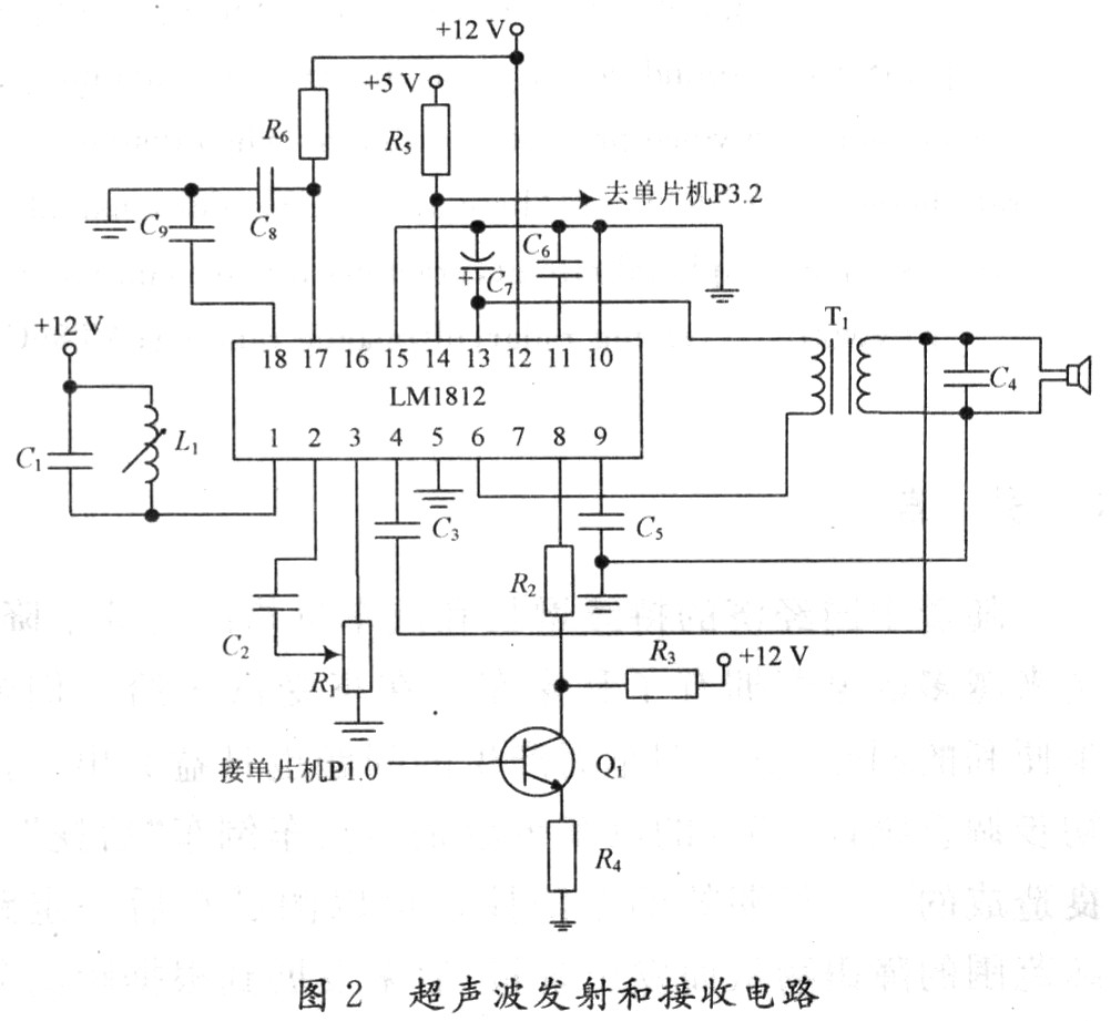
2.3 Ultrasonic transmitting and receiving circuit This system uses ultrasonic special integrated circuit LM1812 as the main control chip of ultrasonic transmitting and receiving circuit. The LM1812 is a general purpose ultrasonic transceiver that is used in a wide variety of ranging, orientation and communication. The chip includes a pulse-modulated Class C transmitter, a high-gain receiver, a pulse-modulated detector, and a noise suppression circuit. The first leg of LM1812 is connected to L1. C1 determines the working frequency of the circuit transmission or reception. Its working frequency is:
![]()
Changing the inductance L1, the value of the capacitor C1 can change the oscillation frequency (f0 is 40 kHz in this system) up to 325 kHz.
The ultrasonic transmitting and receiving circuits are shown in Figure 2. When pin 8 of the LM1812 is high, the LM1812 is in transmit mode; when pin 8 is low, the LM1812 is in receive mode. It is worth noting that the connection from the microcontroller to the LM1812 requires a level shift of 5 to 12 V. When the LM1812 is in the transmit mode, the L1 and C1 oscillation tanks are switched to the oscillation mode. After the oscillation signal is driven and amplified, it is output by pins 13 and 6. The turns ratio of the transformer coil connected between the 6, 13 feet is determined according to the impedance of the TCF40-25TR1 type transceiver integrated ultrasonic sensor. Experiments have shown that the transformer coil has a turns ratio of approximately 4:1 to match the impedance of the ultrasonic transmitter. The ultrasonic signal received by the ultrasonic receiver is input by the 4-pin through capacitive coupling, and then amplified by the internal two-stage amplification and sent to the detector together with the signal taken out by the resonant circuit of the 1-pin. When the ultrasonic echo signal is detected, the 14 pin of the LM1812 (connected to the INT0 terminal of the microcontroller) goes low, causing the T0 counter of the microcontroller to stop counting.
2.4 Temperature compensation circuit The temperature compensation circuit adopts the DS18B20 single-bus digital temperature sensor of DALLAS Semiconductor Company of the United States. A single bus uses only one signal line to transmit data, and the data transmission is bidirectional. The single bus has a "wire and" function, which is convenient for connection and easy to expand. DS18B20 integrates temperature measurement and A/D conversion, and has the advantages of small size, wide dynamic range and high measurement accuracy. DS18B20 and microcontroller interface circuit shown in Figure 3.
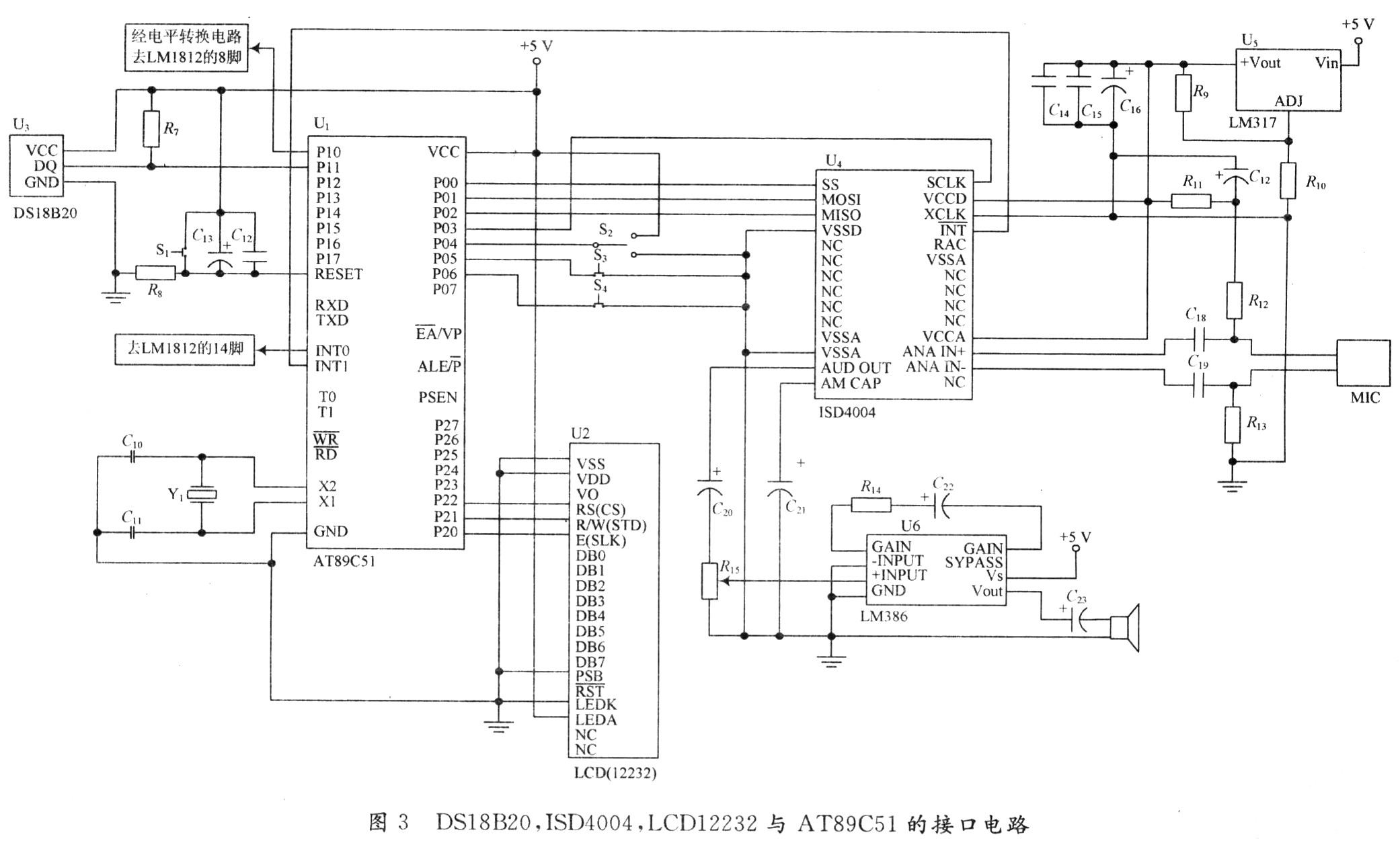
The DS18B20 is connected to the AT89C51 microcontroller in a single bus mode, that is, the DS18B20 has 1 pin grounded, 3 pins grounded, 2 pins connected to the P11 pin of the AT89C51, and the P11 pin is pulled up to VCC with a 4.7 kΩ resistor. The measured temperature value is stored in the 1st and 2nd bytes of the scratchpad memory in the form of a 16-bit signed extended two's complement. After the microcontroller reads the data through the single bus interface, the real-time ambient temperature value can be calculated by calculation. .
2.5 LCD display circuit The system display circuit adopts Jinpeng Electronics' OCMJ12232C_3 liquid crystal display module. This liquid crystal module contains a font library, which can display Chinese characters very conveniently. OCMJ12232C_3 LCD and single-chip AT89C51 interface circuit shown in Figure 3, which OCMJ12232C_3 LCD 15 pin ground, that is, using serial communication. The display includes two parts: the reverse distance and the outside temperature. It is displayed in two lines: the first line shows the reverse distance and the second line shows the outside temperature. The reversing distance is in cm, accurate to 0.1 cm; the temperature is in °C, accurate to O. 1 ° C.
2.6 Voice Alarm Circuit The voice alarm circuit of this system uses ISD4004 voice chip. ISD4004 and microcontroller interface circuit shown in Figure 3. As can be seen from the figure, there is less connection between the ISD4004 and the AT89C51 microcontroller. P00 of the MCU is connected to the chip select pin SS of ISD4004 to control whether the ISD4004 is strobed; P0l is connected to the serial input pin MOSI of ISD4004, and the address of the playback is read from this pin; P02 is connected to the serial output pin MISO of ISD4004. P03 is connected to the serial clock pin SLCK of ISD4004; P04 is connected to the toggle switch for selecting recording or playback; P05 is connected to the STOP button to reset the ISD4004; P06 is connected to the AN button, and the ISD4004 starts to work when pressed; P33 (INT1) is connected to the interrupt pin INT of ISD4004. The connection required for the ISD4004 chip is also the audio signal output pin AUD OUT. This pin is connected to the speaker through a power amplifier circuit LM386 through a filter capacitor; the MIC is connected to the recording signal input terminal of the ISD4004: ANA IN-, ANA IN+); AMCAP is an automatic silent terminal, which is grounded through a capacitor during use. In addition, since the ISD4004 operates at 3 V and the microcontroller requires a supply voltage of 5 V, the LM317 transformer circuit is required to obtain a 3 V voltage for the ISD4004.
When the reversing distance is greater than 3 m, the voice prompt is “reverse safetyâ€; when the reversing distance is between 2 and 3 m, the voice prompt is “reverseâ€; when the reversing distance is between 1 and 2 m, the voice prompt is “Reversing cautionâ€; when the reversing distance is between 0.5 and 1 m, the voice prompt is “reverse dangerâ€; when the reversing distance is less than 0.5 m, the voice prompt is “very dangerous, emergency stopâ€.
3 Software design part The software design adopts modular design, which consists of main program, temperature measurement and sound speed correction subroutine, T0 interrupt subroutine, distance calculation subroutine, LCD display subroutine and voice alarm subroutine. The main program flow chart is shown in Figure 4.
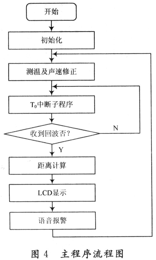
After the program is initialized, the temperature measurement and sound speed correction subroutine are called to correct the sound speed. When performing ultrasonic ranging, the microcontroller sends a pulse signal with a width of 125 μs, which controls the ultrasonic integrated circuit LM1812 to emit five 40 kHz ultrasonic pulse trains. The T0 timer is timed 30 ms, ie five 40 kHz ultrasonic bursts are transmitted every 30 ms. While transmitting the pulse train, the T0 counter of the MCU starts counting, and stops counting as soon as the echo signal is received. After the measured time and the corrected sound speed are processed by the distance calculation subroutine, the result is sent to the LCD display and the voice alarm is performed.
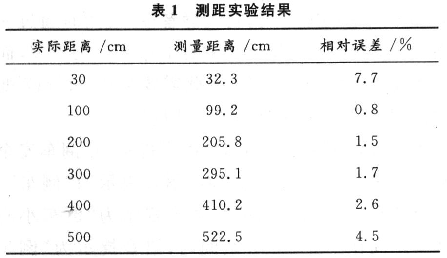
4 Experimental results Through multiple measurements on planar objects, it is found that accurate distance measurement can be achieved in the range of 30 to 500 cm, which can meet the driver's reversing requirements. The ranging results are shown in Table 1.
5 Conclusion <br> The reversing radar system designed in this paper adopts AT89C51 as the main control chip, which can realize real-time ultrasonic ranging and display the measured distance on the LCD. At the same time, different voices are used for different distance segments through the voice alarm circuit. Prompt, the experiment verified the feasibility and reliability of the system. The system has the characteristics of high integration, wide measuring range, low cost and convenient use, which can meet the needs of drivers in reversing and can be widely used.
LED Light Bulbs,LED Bulb,LED Corn Bulb
LED Spotlight,LED Panel Light Co., Ltd. , http://www.cnledspotlight.com