
In the fields of industrial control, power communication, and smart metering, serial communication is widely used for data exchange. The initial interface adopted was RS232. However, due to the complex environments found in industrial settings—where various electrical devices generate significant electromagnetic interference—the signal transmission can be prone to errors. Additionally, the RS232 interface only supports point-to-point communication, lacks networking capabilities, and has a maximum transmission distance of just tens of meters, which is insufficient for long-distance applications. To address these limitations, RS485 was introduced. It uses differential signaling, which effectively suppresses common-mode interference. With a maximum transmission distance of up to 1200 meters, it allows multiple transceivers to connect on the same bus. In 1979, Schneider Electric developed the Modbus protocol to meet the growing needs of industrial communication. Today, many RS485-based systems use the Modbus protocol. This article explores RS485 communication and the Modbus protocol in detail.
**Key Features of RS485**
1. One of the most significant advantages of RS485 is its ability to suppress common-mode interference through differential signaling. In industrial environments, where electromagnetic noise is prevalent, this feature ensures more reliable communication. RS485 uses two wires, typically labeled A and B or D+ and D-, to transmit signals. A logic '1' is represented by a voltage difference of +0.2V to +6V between the two lines, while a logic '0' is represented by a voltage difference of -0.2V to -6V. This differential approach makes it highly resistant to noise.
2. RS485 supports high-speed data transmission, with a maximum speed of up to 10 Mbps. However, as the speed increases, the maximum transmission distance decreases.
3. The internal structure of RS485 consists of a balanced driver and a differential receiver, significantly enhancing its anti-interference capability.
4. The maximum transmission distance can reach up to 1200 meters, but this is inversely related to the communication speed. For longer distances, a repeater can be used to extend the range.
5. RS485 allows for multi-device communication over a single bus. Multiple transceivers can be connected, and depending on the chip, the number of supported devices can vary from 32 to 256.
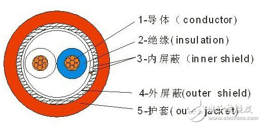
*RS485 communication cable structure diagram*
The RS485 interface is relatively simple, similar to the MAX232 used in RS232. It only requires an RS485 converter to connect to the UART serial interface of a microcontroller, using asynchronous serial communication. However, since it's a differential communication method, it operates in half-duplex mode, meaning that data cannot be both received and transmitted at the same time.
**Modbus Protocol Features**
Modbus is a versatile communication protocol widely used in industrial automation. It enables controllers to communicate with each other and with other devices over networks such as Ethernet. It has become an industry standard, allowing equipment from different manufacturers to be integrated into a unified network for centralized monitoring.
The protocol defines a standardized data structure that all devices can recognize, regardless of the communication network they are using. It outlines how controllers request access to other devices, respond to requests, and detect errors. It also sets a common format for the structure and content of communication data.
In multi-device communication, each device must have a unique address. When a controller sends data, it includes the address of the target device. The receiving device checks the address, processes the request, and responds accordingly. If an error occurs, no response is sent.
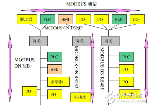
Modbus supports flexible communication across various network architectures. Each device, such as a PLC, HMI, or I/O module, can initiate remote operations using the Modbus protocol. Some gateways even allow communication between different buses or networks using Modbus.
**Communication Instructions**
Controllers using the RS-485 bus follow the Modbus RTU protocol. Data is transmitted in 8-bit data bits, with 1 stop bit and no parity. The baud rate can be set between 1200 and 9600 bps. Communication is divided into headers and encoded data.
The communication frame includes the following elements:
- **Address Code**: The first byte of the message, indicating the destination device.
- **Function Code**: The second byte, specifying the action to be taken.
- **Data Area**: Contains the actual data being transmitted, varying based on the function code.
- **CRC Code**: A 16-bit cyclic redundancy check for error detection.
When a command is sent, the device with the matching address receives it, processes the request, and returns the result. The response includes the address, function code, data, and CRC. If an error occurs, no response is sent.
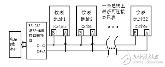
**Wiring Instructions**
Here is a wiring diagram showing how multiple devices can be connected on a single RS485 bus.
Linear Actuators,Column Lift Linear Actuator,Motorized Linear Actuator,High Speed Linear Actuator
Kunshan Zeitech Mechanical & Electrical Technology Co., Ltd , https://www.zeithe.com