Common-mode chokes, also known as common-mode inductors, are widely used in computer power supplies to suppress electromagnetic interference (EMI) signals that appear on both the line and neutral wires. These components act as EMI filters, preventing high-speed signal lines from radiating unwanted electromagnetic energy. In PCB design, they play a crucial role in reducing noise and improving signal integrity.
The basic principle of a common-mode choke involves two windings placed on the same magnetic core, wound in opposite directions. When a differential mode signal is applied, the magnetic fields cancel each other out, allowing the signal to pass through with minimal resistance. However, when a common-mode signal is present, the magnetic fields reinforce each other, creating a higher impedance that effectively blocks the interference.
Inductors are essential components in power electronics, especially in power circuits where they are used for filtering, energy storage, and power factor correction. They are found in various applications such as relays, electric meters, and switching power supplies. The design of inductors requires careful consideration of parameters like current, voltage, frequency, temperature, and material properties.
Common-mode chokes can be classified based on their application and structure. They include normal-mode chokes, PFC chokes, coupling chokes, and energy storage inductors. The most common type is the toroidal inductor, which offers good symmetry and low leakage inductance. Designing a common-mode choke involves selecting the right core material, determining the number of turns, and ensuring proper insulation and thermal management.
When designing a common-mode choke, it's important to ensure that the core does not saturate under normal operating conditions. The inductor should have sufficient impedance at high frequencies while maintaining low resistance at the operating frequency. Additionally, minimizing distributed capacitance helps improve high-frequency noise suppression.
In practical designs, the inductance value is calculated based on the desired cutoff frequency and the capacitance of the filter. For example, if a cutoff frequency of 50 kHz is required, the inductance can be calculated using the formula: L = 1 / (4π²f²C). This ensures that the filter effectively attenuates unwanted noise without affecting the desired signal.
Finally, real-world testing is essential to validate the performance of the inductor. Variations in manufacturing processes can affect the inductance and symmetry of the windings, which may impact the overall filtering effectiveness. Therefore, thorough testing and optimization are necessary to achieve reliable EMI suppression in power supply systems.
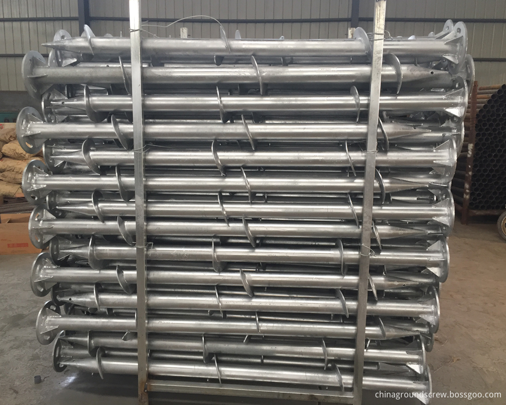
Flanged Ground Screw For Solar Mounting
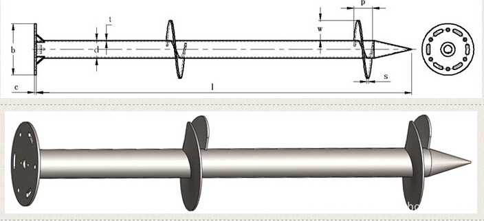
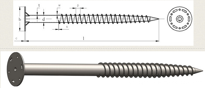
Flanged Ground Screw for solar energy mounting system .different size flange ( head plate ) ,usualy flange size is 220*8mm ,200*8mm ,with square flange,round flange,hexagon flange ,triangle flange .
Helix flanged ground screw made of carbon steel Q235 ,standard of DIN EN ISO 1461-1999 .
Flange Ground screw parameter are as below :
Ground screw pipe diameter :60mm,68mm,76mm,89mm,102mm,114mm
Ground Screw pipe thickness :2.5mm,2.75mm,3.00mm,3.75mm,4.00mm,4.5mm
Ground Screw Pile length : 1000mm,1200mm,1400mm ,1500mm,1600mm,1800mm,2000mm,2100mm,2500mm,2700mm,3000mm .
Ground Screw material : carbon steel Q235
Surface treatment : hot dip galvanized .according to standard :DIN EN ISO1461-1999 ,average thickness of zinc coating :85micron
Drawing force parameter :10.7-28.5KN
Bearing capacity :20-40KN
Horizontal torsion parameters :4.5-10.5KN
packing :steel pallet


Solar Ground Screw,Ground Screw For Solar Mounting,Solar Panel Ground Screw,Solar Bracket Ground Screw
BAODING JIMAOTONG IMPORT AND EXPORT CO., LTD , https://www.chinagroundscrew.com


