
This paper discusses the electromagnetic disturbance EMD and electromagnetic sensitivity EMS design issues for electromagnetic compatibility of switching power supplies. Since the country has begun to enforce 3C certification for some electronic products, whether an electronic device can meet the electromagnetic compatibility standard will affect whether the product can be sold in the market. Therefore, it is very important to conduct electromagnetic compatibility research on the switching power supply.
Electromagnetic compatibility is a comprehensive discipline, which involves mathematics, electromagnetic field theory, antenna and wave propagation, circuit theory, signal analysis, communication theory, materials science, and biomedicine.
When designing the electromagnetic compatibility of the switching power supply, first design a system to clarify the following points:
1. Identify the electromagnetic compatibility standards to be met by the system;
2. Identify critical circuit components within the system, including strong interference source circuits and highly sensitive circuits;
3. Identify the sources of electromagnetic interference and sensitive equipment in the working environment of the power supply equipment;
4. Determine the electromagnetic compatibility measures to be taken for the power supply unit.
I. Analysis of internal noise interference sources in DC/DC converters
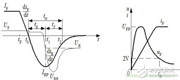
1. Reverse recovery of the diode causes noise interference
Power frequency rectification diodes, high frequency rectification diodes, freewheeling diodes, etc. are often used in switching power supplies. Since these diodes are all in the switching state, as shown in the figure, during the diode from blocking state to conduction, a Very high voltage spike VFP; there is a reverse recovery time trr during the diode's conduction state to blocking operation. During the reverse recovery process, due to the diode package inductance and lead inductance, a reverse will occur. The voltage spike VRP, due to the storage and compounding effect of the minority, generates a transient reverse recovery current IRP. This rapid current and voltage abrupt change is the source of electromagnetic interference.
Current and voltage waveform
Current and voltage waveform diode forward conduction current voltage waveform when diode reverse recovery
2. Electromagnetic interference occurs when the switch is switched
Current and voltage waveform diode forward conduction current voltage waveform when diode reverse recovery
In forward-excitation, push-pull, and bridge converters, the current waveform flowing through the switching tube approximates a rectangular wave during a resistive load, and is rich in high-frequency components. These high-frequency harmonics generate strong electromagnetic interference. In the flyback converter, the current waveform flowing through the switching tube approximates a triangular wave at a resistive load, and the harmonic component is relatively small. When the switch is turned on, due to the short switching time and the presence of lead inductance in the inverter circuit, a large dV/dt abrupt change and a high peak voltage will be generated. When the switch is turned off, the turn-off time is very high. Short, will produce large di / dt mutations and high current spikes, these current, voltage mutations will produce strong electromagnetic interference.
3. Electromagnetic interference caused by magnetic components such as inductors and transformers: There are input filter inductors, power transformers, isolation transformers, output filter inductors and other magnetic components in the switching power supply. Parasitic capacitance exists between the primary and secondary of the isolation transformer, and the high-frequency interference signal passes through the parasitic capacitance. Coupling to the secondary side; power transformer due to the winding process and other reasons, the original secondary coupling is not ideal and there is leakage inductance, the leakage inductance will generate electromagnetic radiation interference, and the power transformer coil winding flows through the high frequency pulse current, forming a high frequency around Electromagnetic field; the pulsating current flowing through the inductor coil generates electromagnetic field radiation, and when the load is cut, a voltage spike is formed, and when it is operating in saturation, a sudden change in current will occur, which will cause electromagnetic interference.
4. Periodic high-frequency pulse signals in the control circuit, such as high-frequency pulse signals generated by the oscillator, will generate high-frequency harmonics and cause electromagnetic interference to surrounding circuits.
5. In addition, there will be ground loop interference, common impedance coupling interference, and control power supply noise interference.
6. The wiring design in the switching power supply is very important. Unreasonable wiring will cause electromagnetic interference to crosstalk or radiate to the adjacent wires through the coupling capacitance and distributed mutual inductance between the wires, thus affecting the normal operation of other circuits.
7. Electromagnetic interference generated by thermal radiation, which is heat exchange in the form of electromagnetic waves, which affect the normal and stable operation of other electronic components or circuits.
Second, the external electromagnetic interference
For an electronic device, external electromagnetic interference affects it: harmonic interference in the power grid, lightning, solar noise, electrostatic discharge, and interference caused by surrounding high-frequency transmitting equipment.
Third, the consequences of electromagnetic interference
Electromagnetic interference will cause distortion of the transmission signal and affect the normal operation of the equipment. For high-energy electromagnetic interference such as lightning and electrostatic discharge, the device may be damaged in severe cases. For some devices, electromagnetic radiation can cause leakage of important information.
Fourth, the electromagnetic compatibility design of the switching power supply
After understanding the internal and external sources of electromagnetic interference from the switching power supply, we should also know that the three elements that form the electromagnetic interference mechanism are the propagation path and the disturbed equipment. Therefore, the electromagnetic compatibility design of the switching power supply mainly starts from the following three aspects: 1. Reduce the electromagnetic interference energy of the interference source; 2. Cut off the interference propagation path; 3. Improve the anti-interference ability of the victim device.
It is very important to understand and understand the electromagnetic interference source of the switching power supply and its generation mechanism and interference propagation path. It is very important to take anti-interference measures to make the equipment meet the electromagnetic compatibility requirements. Since the interference source has an interference source generated inside the switching power supply and an external interference source, and it can be said that the interference source cannot be eliminated, the victim device is always present, so it can be said that the electromagnetic compatibility problem always exists.
The following is an example of an isolated DC/DC converter to discuss the electromagnetic compatibility design of a switching power supply:
1. Design of DC/DC converter input filter circuit
As shown in the figure, FV1 is a transient voltage suppression diode and RV1 is a varistor. Both have strong transient surge current absorption capability, which can protect the downstream components or circuits from surge voltage. . Z1 is a DC EMI filter. It must be well grounded. The grounding wire should be short. It is best to install it directly on the metal casing. It must also ensure the shielding isolation between its input and output lines to effectively cut off the propagation of conducted interference along the input line. And the propagation of radiation interference along the space. L1 and C1 form a low-pass filter circuit. When the inductance value of L1 is large, it is necessary to increase the V1 and R1 components as shown in the figure to form the electric field energy released by the freewheeling circuit to absorb L1 disconnection. Otherwise, the voltage spike generated by L1 is generated. Electromagnetic interference will be formed. The magnetic core used in the inductor L1 is preferably a closed magnetic core. The leakage magnetic field of the open-loop magnetic core with air gap will form electromagnetic interference, and the capacity of C1 is large, so that the input line can be reduced. The ripple voltage on the ground, thereby reducing the electromagnetic field formed around the input conductor.
Electromagnetic compatibility is a comprehensive discipline, which involves mathematics, electromagnetic field theory, antenna and wave propagation, circuit theory, signal analysis, communication theory, materials science, and biomedicine.
When designing the electromagnetic compatibility of the switching power supply, first design a system to clarify the following points:
1. Identify the electromagnetic compatibility standards to be met by the system;
2. Identify critical circuit components within the system, including strong interference source circuits and highly sensitive circuits;
3. Identify the sources of electromagnetic interference and sensitive equipment in the working environment of the power supply equipment;
4. Determine the electromagnetic compatibility measures to be taken for the power supply unit.
I. Analysis of internal noise interference sources in DC/DC converters
1. Reverse recovery of the diode causes noise interference
Power frequency rectification diodes, high frequency rectification diodes, freewheeling diodes, etc. are often used in switching power supplies. Since these diodes are all in the switching state, as shown in the figure, during the diode from blocking state to conduction, a Very high voltage spike VFP; there is a reverse recovery time trr during the diode's conduction state to blocking operation. During the reverse recovery process, due to the diode package inductance and lead inductance, a reverse will occur. The voltage spike VRP, due to the storage and compounding effect of the minority, generates a transient reverse recovery current IRP. This rapid current and voltage abrupt change is the source of electromagnetic interference.
Current and voltage waveform
Current and voltage waveform diode forward conduction current voltage waveform when diode reverse recovery
2. Electromagnetic interference occurs when the switch is switched
Current and voltage waveform diode forward conduction current voltage waveform when diode reverse recovery
In forward-excitation, push-pull, and bridge converters, the current waveform flowing through the switching tube approximates a rectangular wave during a resistive load, and is rich in high-frequency components. These high-frequency harmonics generate strong electromagnetic interference. In the flyback converter, the current waveform flowing through the switching tube approximates a triangular wave at a resistive load, and the harmonic component is relatively small. When the switch is turned on, due to the short switching time and the presence of lead inductance in the inverter circuit, a large dV/dt abrupt change and a high peak voltage will be generated. When the switch is turned off, the turn-off time is very high. Short, will produce large di / dt mutations and high current spikes, these current, voltage mutations will produce strong electromagnetic interference.
3. Electromagnetic interference caused by magnetic components such as inductors and transformers: There are input filter inductors, power transformers, isolation transformers, output filter inductors and other magnetic components in the switching power supply. Parasitic capacitance exists between the primary and secondary of the isolation transformer, and the high-frequency interference signal passes through the parasitic capacitance. Coupling to the secondary side; power transformer due to the winding process and other reasons, the original secondary coupling is not ideal and there is leakage inductance, the leakage inductance will generate electromagnetic radiation interference, and the power transformer coil winding flows through the high frequency pulse current, forming a high frequency around Electromagnetic field; the pulsating current flowing through the inductor coil generates electromagnetic field radiation, and when the load is cut, a voltage spike is formed, and when it is operating in saturation, a sudden change in current will occur, which will cause electromagnetic interference.
4. Periodic high-frequency pulse signals in the control circuit, such as high-frequency pulse signals generated by the oscillator, will generate high-frequency harmonics and cause electromagnetic interference to surrounding circuits.
5. In addition, there will be ground loop interference, common impedance coupling interference, and control power supply noise interference.
6. The wiring design in the switching power supply is very important. Unreasonable wiring will cause electromagnetic interference to crosstalk or radiate to the adjacent wires through the coupling capacitance and distributed mutual inductance between the wires, thus affecting the normal operation of other circuits.
7. Electromagnetic interference generated by thermal radiation, which is heat exchange in the form of electromagnetic waves, which affect the normal and stable operation of other electronic components or circuits.
Second, the external electromagnetic interference
For an electronic device, external electromagnetic interference affects it: harmonic interference in the power grid, lightning, solar noise, electrostatic discharge, and interference caused by surrounding high-frequency transmitting equipment.
Third, the consequences of electromagnetic interference
Electromagnetic interference will cause distortion of the transmission signal and affect the normal operation of the equipment. For high-energy electromagnetic interference such as lightning and electrostatic discharge, the device may be damaged in severe cases. For some devices, electromagnetic radiation can cause leakage of important information.
Fourth, the electromagnetic compatibility design of the switching power supply
After understanding the internal and external sources of electromagnetic interference from the switching power supply, we should also know that the three elements that form the electromagnetic interference mechanism are the propagation path and the disturbed equipment. Therefore, the electromagnetic compatibility design of the switching power supply mainly starts from the following three aspects: 1. Reduce the electromagnetic interference energy of the interference source; 2. Cut off the interference propagation path; 3. Improve the anti-interference ability of the victim device.
It is very important to understand and understand the electromagnetic interference source of the switching power supply and its generation mechanism and interference propagation path. It is very important to take anti-interference measures to make the equipment meet the electromagnetic compatibility requirements. Since the interference source has an interference source generated inside the switching power supply and an external interference source, and it can be said that the interference source cannot be eliminated, the victim device is always present, so it can be said that the electromagnetic compatibility problem always exists.
The following is an example of an isolated DC/DC converter to discuss the electromagnetic compatibility design of a switching power supply:
1. Design of DC/DC converter input filter circuit
As shown in the figure, FV1 is a transient voltage suppression diode and RV1 is a varistor. Both have strong transient surge current absorption capability, which can protect the downstream components or circuits from surge voltage. . Z1 is a DC EMI filter. It must be well grounded. The grounding wire should be short. It is best to install it directly on the metal casing. It must also ensure the shielding isolation between its input and output lines to effectively cut off the propagation of conducted interference along the input line. And the propagation of radiation interference along the space. L1 and C1 form a low-pass filter circuit. When the inductance value of L1 is large, it is necessary to increase the V1 and R1 components as shown in the figure to form the electric field energy released by the freewheeling circuit to absorb L1 disconnection. Otherwise, the voltage spike generated by L1 is generated. Electromagnetic interference will be formed. The magnetic core used in the inductor L1 is preferably a closed magnetic core. The leakage magnetic field of the open-loop magnetic core with air gap will form electromagnetic interference, and the capacity of C1 is large, so that the input line can be reduced. The ripple voltage on the ground, thereby reducing the electromagnetic field formed around the input conductor.
Vacuum Cleaner Dc Dry Motor,Dry Brushed Vacuum Cleaner Motor,Brushless Vacuum Cleaner Motor,Dry Ac/Dc Vacuum Cleaner Motor
Zhoushan Chenguang Electric Appliance Co., Ltd. , https://www.vacuum-cleaner-motors.com