
The voltage type single loop circuit is simple to control and is the most widely used in various fields. When applied to a small power switching power supply, the compensation network can be easily implemented by comparing the voltage division feedback with the reference amplification. In the high-power circuit, the calibration is very difficult and the accuracy is insufficient. Currently only satisfied with repeated debugging, time-consuming and laborious.
1 Structure and principle of voltage type PWM inverter control system
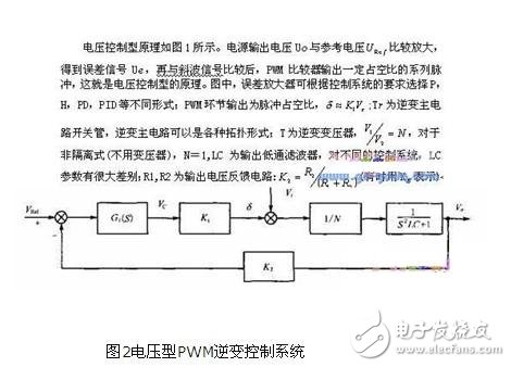
The final output of the inverter control system can be DC voltage, AC voltage, DC current, AC current, frequency or power, and filtering is required in the output part. Most of the inverter system output is DC voltage, that is, the system output and regulation is the amount of DC voltage. Of course, the secondary side of the inverter transformer also has a rectifier circuit. The pulse width modulation (PWM) type switching regulator power supply only samples the output voltage and implements closed-loop control. This control mode is a voltage control type and is a single-loop control system. For these systems, the feedback amount is a certain proportional value of the output voltage. The error signal of the given voltage and the feedback voltage is used to adjust the width of the PWM pulse. We usually refer to this inverter control system as a voltage-type PWM control system. For most voltage-type PWM inverter control systems, whether it is DC output or AC output, the structural block diagram of the control system can be uniformly drawn as shown in Figure 1.
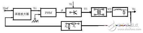
Figure 1 Block diagram of voltage type PWM inverter control system
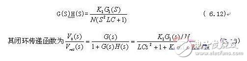
The open-loop transfer function G(S)H(S) of the inverter system is given by:
The biggest disadvantage is that the current value in the power circuit is not involved in the control process. It is well known that the output current of a switching power supply is to flow through the inductor, so there is a phase delay of 90 degrees for the voltage signal. However, for a regulated power supply, the current should be considered to accommodate the change of the output voltage and the load demand. Therefore, the purpose of stabilizing the output voltage is achieved. Therefore, only the output voltage sampling method is adopted, and the response speed is slow, the stability is poor, and even when a large signal changes, oscillation occurs, causing damage such as power tube damage.
2. System analysis and design
If the error amplifier (or regulator) is a proportional link, equations (6.12) and (6.13) are second-order, that is, the system is a second-order system. The second-order system is a conditionally stable system. In addition, since the output filter parameter LC is generally large, the frequency parameter is relatively low.
Therefore, the system crosses the line L(ω)=0 at a mid-band with a slope of -40dB/dec. In this system, even with the PI regulator, it is only to reduce the steady-state error. Therefore, the zero point is also very low, and the mid-band still crosses the zero line with a slope of -40dB/dec, as shown in Figure 3.
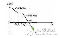
Figure 3 amplitude-frequency characteristic curve of voltage-type PWM inverter control system
In order for the system to meet the requirements of steady state performance, dynamic performance and stability, it is necessary to make corrections in the system. Obviously, in the middle frequency band, adding a series of lead correction (active or passive) as shown in Figure 4, can make the low, medium and high frequency bands of the open-loop amplitude-frequency characteristics meet the requirements, as shown in Figure 4. .
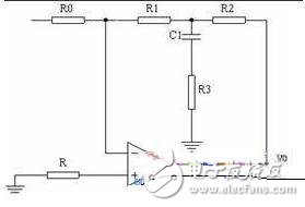
Figure 4 correction network
3. Join the compensation network
At the partial pressure feedback, due to the hysteresis of the inductor voltage, a resistor and a capacitor branch are connected in parallel at the feedback, and the feedback voltage can instantaneously reflect the change of the output voltage through the lead of the capacitor voltage. Since the ratio of R1 and R2 is large, a weak change in the output is sensed by a capacitor connected in parallel across R2.
Its amplitude-frequency characteristic curve is as follows:
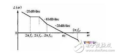
Fig.5 Amplitude-frequency characteristic curve of voltage-type PWM inverter control system with correction link

Safety Light Curtain,Safety Curtain,Laser Safety Light Curtain,Safety Optic Light Curtain,Security Light Curtain,Press Brake Safety Light Curtains
Jining KeLi Photoelectronic Industrial Co.,Ltd , https://www.sdkelien.com