
Abstract: Small engine manufacturers are beginning to face pressure from global government legislators that require them to increase product efficiency and reduce emissions. In order to meet regulatory requirements, the engine control system must be converted from mechanical control to electronic control. Some of the lessons learned from automotive engines in the transition from mechanical control to electronic control apply to small engines. Recent advances in circuit integration have enabled small engine manufacturers to develop electronic controls that make their products “greenerâ€. This article will briefly describe some of the necessary transformations and what Freescale has done to help make this conversion easy, cost-effective, and cost-effective.
This article refers to the address: http://
introduction
Two recent events have led small engine manufacturers to consider replacing traditional mechanical engines with newer, more affordable electronic controls.
Environmental conditions
Severe pollution in urban areas, as well as emissions from motorcycles and other small engine vehicles, have led to a growing “greenhouse effect†that has forced many governments to begin to develop stricter emissions regulations. These new regulations are specific to small internal combustion engines. Manufacturers need to replace mechanical engine controls with electronic controls if they meet the exhaust emission standards required by these regulations. But small engine control systems are demanding in terms of target cost and size requirements, which requires manufacturers to seek innovative design solutions to implement these electronic controls.
Fuel efficiency
The cost of a gallon of gasoline has increased from 20 cents in 1956 to nearly $4, the current highest point. The instability of the global crude oil production has caused the price of this necessities to change frequently. Previously considered to be an infinite supply of crude oil, oil companies believe that one day it will also be used up. Extending fuel supply time and reducing engine operating costs means that all engines, regardless of size, require a more fuel efficient design.
2 or 4 stroke engine
One major difference between some small engines and large engines is the number of "strokes" or the number of times the piston needs to complete a cycle in the cylinder. If it is not within the pros and cons of the two engines discussed in this article, it is enough to show that the low-cost fuel use is now used, and the 2-stroke engine must be completely redesigned to meet the new emission regulations.
Mechanical control
Nikolai Otto invented the traditional internal combustion engine in 1876. The operation of the internal combustion engine depends on three factors: air, fuel and combustion. In the cylinders of the engine, the spark-point gas/oil mixture is precisely controlled at a time, and then the combustion moves to push the pistons down in the cylinder, causing the engine crankshaft to rotate. The mechanical control system of a small internal combustion engine includes two mechanical components and one electronic component. The first mechanical component (ie, the carburetor) uses the vacuum created in the cylinder. Because the engine initially turns the crankshaft through the starter motor, drawstring or pedal starter to absorb and atomize the fuel, allowing the oil and gas to mix in the correct ratio. The oil/gas mixture is drawn into the cylinder through the second mechanical component (ie, the intake valve) at the appropriate time. The only electronic component known as the "magneto" is used to generate a precise time-controlled spark that is determined by the two magnets attached to the flywheel of the rotating crankshaft. The mechanical control system is basically an extended system of "open loop circuits", which means that no feedback is provided in the engine to indicate whether the mechanical control system is operating normally; if not, correct it. In order to increase efficiency and reduce emissions, a "closed loop" type of control system must be provided. In theory, it is feasible to design a closed-loop mechanical feedback system, but it is unrealistic according to the new microcomputer-controlled electronic system currently used in the automotive market.
Electronic control
The transition from mechanical control systems to electronic control systems consists of two main aspects: spark control and fuel control. In addition, it introduces a closed-loop control concept and an oxygen sensor feedback signal that monitors engine exhaust. If oxygen is present in the exhaust gas, it indicates that the cylinder combustion reaction has not reached the normal ratio of air and fuel of 14.7:1, or that the combustion reaction has not been completed for some reason.
Spark control
In the transition from mechanical control to electronic control, the biggest shift is from a simple magneto-driven spark generation system to a microcomputer-controlled spark ignition system.
The magneto is basically a 100:1 booster with a main power switch. When the flywheel rotates and the first magnet passes through the magnet core, the magnets embedded in the engine flywheel sense the current generated in the mains. The second magnet turns the main power switch on. The resulting magnetic collapse magnetic field generates a 200V pulse in the main power source. A 100:1 boost ratio magneto motor causes a 200 volt pulse to rise to 20,000 volts in the backup power source from primary to backup power, which can cause sparks in the spark plug gap. The magneto is simple and reliable, but if the magnet position or magnet position cannot be actually moved, it is impossible to control the spark output in time.
A fire wreath is similar to a magneto. It is also a booster, but instead of using a magnet, it uses a battery/alternator to supply the mains current to create a magnetic field that can generate high-voltage pulses. In addition, it does not use a magnetically triggered main switch to disconnect primary current and generate magnetic collapse, but uses a semiconductor device, a Darlington bipolar junction transistor or the latest insulated gate bipolar transistor (IGBT).
In magneto-electric systems, the magnets embedded in the flywheel also provide the timing signals needed to generate sparks at fixed times during the engine's compression cycle. In an induction coil based system, multiple gears attached to the crankshaft and an induction coil called a "variable magnetoresistive sensor (VRS)" collectively provide a reference timing signal to the microcomputer, which is then at a given engine speed. The best time for loading, temperature and temperature emits a spark signal to maximize efficiency and reduce contaminants. Changes in fuel quality can be adjusted by changing the spark timing. The calibration table stored in the microcomputer's memory allows the microcomputer to monitor the sensor's output based on various engine parameters to find the appropriate time to generate the spark.
Fuel control
Carburetors have a history of more than 100 years of evolution, so most small engine manufacturers are reluctant to replace them with relatively new developments, fuel injectors. The current trend in small engines is to use a hybrid approach called "electronic carburetor." It eliminates several purely mechanical parts of a conventional carburetor with an electronically controlled solenoid or motor. Unlike the transition from magneto to sparkle and microcomputer ignition control, the transition from carburetor to injector simplifies many aspects of the fuel system design. Instead of relying on engine vacuum to provide the oil and gas mixture to the cylinder, the injector relies on the fuel pressure from the pump to atomize the fuel through a solenoid-controlled injector. By distributing the fuel by pulse and by the microcomputer, this allows more precise control of the fuel quantity and optimizes fuel delivery time to increase the efficiency of the combustion process. In addition, it allows the microcomputer to adjust the fuel/air mixing ratio based on feedback from oxygen and other engine parameter sensors.
Electronic engine control unit
The electronic engine control unit (or ECU) is a module consisting of a microcomputer (MCU) and all the analog-digital interface circuits required to implement the engine control strategy. A common single-cylinder ECU block diagram is shown below:

Figure 1 Small engine ECU block diagram
MCUs are typically CMOS 8- or 16-bit devices that can easily handle the specified arithmetic and logic functions. Due to the voltage/current drive limitations of the MCU output and the sensitivity of the input, an analog circuit must be provided at the interface between the various sensors of the engine, the electromechanical actuator, and the I/O pins of the MCU. In addition, the MCU power regulation and the specified reset signal also require an analog circuit.
The challenge for small engine ECU designers is how to reduce the size of the ECU so that it can be mounted on a small engine. This is certainly not a problem for large motorcycles or industrial generators, but for small handheld power tools such as weeders and leaf blowers, the size and weight of the ECU is part of the overall tool. In order to reduce size and weight, the number of various parts of the ECU must be minimized. Since the digital components of the ECU, the MCU, occupy a small fraction of the overall size and weight, other analog components must be similarly integrated to reduce size and weight.
Single cylinder engine ASSP
For this purpose, Freescale Semiconductor recently introduced an ASSP (first application-specific standard product) IC to integrate multiple analog functions of a small engine onto a single chip. The IC's part number is MCZ33812, which is aimed at small single or twin cylinder engines. It integrates a single IC, MCU power regulator, reset and watchdog functions, serial IS09141 interface for diagnostic communication, an ignition pre-driver, and an injector drive that can be used to drive relays or alternate injections The two low-side drivers of the unit, as well as an indicator that displays an abnormal function. It is a very basic feature set, but for this reason it can be used for high volume production of single cylinder small engine ECUs.
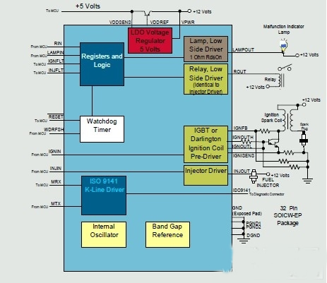
Figure 2 MCZ33812 block diagram
MCZ33812 details
The MCZ33812 integrates multiple analog functions into a small 32-pin package. The interface between the MCU and the IC passes through 10 parallel 5V logic level lines. The reason for choosing a simple parallel interface is to ensure that even a new electronic design engineer can change the circuit design. The circuit is designed to operate from a standard 12 volt battery, but can withstand up to 36V, and all external outputs prevent battery shorts, over currents, over temperature and ESD issues. The features included are briefly described below:
power supply
The module is a linear regulator pre-driver that provides a stable 5V supply to power the MCU. It is designed to provide a stable 5V supply from an output voltage of *V to 36V and to track input voltage supplies from *V to 4.5V. As a pre-driver, it drives the base of the external PNP transistor, generating a 5V voltage with a floating range of +/- 2% at the collector. The VCCSENS input pin is connected to the PNP collector, which monitors the feedback output voltage and regulates the collector at 5V.
Reset and safety features
To ensure that the MCU is functioning properly, the IC must have certain security features. The first reset circuit with output pin RESETB, which can drive the reset input pin of the MCU. There are a total of three different events that can cause a reset signal to occur. The reset module consists of three input pins: one is VCCSENS to sense the external 5V voltage; the other is WDRFSH, which is used to periodically provide the refresh signal from the MCU to the watchdog timer; the last one is WD_INH, which is used to select whether to enable or disable Disable the watchdog function. The first event that may drive the reset signal is a power-on reset. When the device first powers up, the RESETB signal is asserted low to ensure that the MCU remains in reset until the supply voltage reaches the minimum operating value. When the 5V voltage exceeds the lowest level, the RESETB signal can be held at a low position for another 128 microseconds, which stabilizes the internal logic time of the MCU. After 128 microseconds, the RESETB signal is asserted high and the MCU begins executing the program. The second case in which the RESETB signal occurs is a Brown-out Reset, which occurs when the 5V voltage is below the minimum operating value of the MCU. This will ensure that the MCU will not operate after it exceeds the recommended operating voltage range. The last case in which the RESETB signal is generated is a watchdog circuit timeout reset. When the watchdog circuit is enabled, the WDRFSH pin periodically provides a refresh signal from the MCU. If the MCU cannot provide a periodic refresh signal, it indicates that the program instruction stream has an error or the MCU has "hanged up". After the RESETB condition occurs, the maximum duration of the watchdog is determined by the length of time the first pulse is supplied by the MCU on the WDRFSH pin.
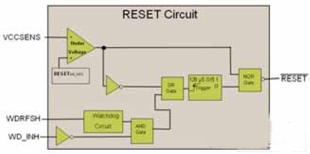
Figure 3 MCZ33812 reset circuit block diagram
Ignition pre-driver
The ignition pre-driver can drive IGBT or Darlington transistors. It has two output lines, the IGNOUTH and IGNOUTL lines, controlled by a single parallel input pin, IGNIN. The type of transistor used can be determined by the connected IGNSUP pin: either a Darlington transistor can be selected to provide 5V or an IGBT can be selected to provide 12V. Most new car designers choose to use IGBTs, but some small engine ECU designers still use Darlington transistors because the previous CDI ECU designs used Darlington transistors. After the ignition pre-drive device detects an open circuit fault or a battery short circuit, the fault indication signal IGNFLT is sent to the MCU.
Low side drive
It has three low-side drivers, all controlled with associated parallel input pins. They are designed to drive injectors, relays (or alternate injectors), and warning lights or other loads.
The low-side drivers are turned off during overvoltage or undervoltage events, and they all prevent overcurrent, short-to-battery, and over-temperature conditions. For injectors and relay drives, no-load or battery short-circuit faults can be detected. The injector and relay drive provide a fault reporting signal to the MCU.
The relay drive has the same electrical characteristics as the injector drive, so it can also be used to drive other higher current devices such as fuel pumps.
The indicator driver has no fault indication signal, but it prevents overcurrent, overvoltage, overtemperature, and battery shorts. Because it has no pins to provide fault information to the microcontroller, the drive is turned off when a fault condition is detected; when the fault condition disappears, it turns back on. But it is designed to drive incandescent lamps because its maximum current limit is 3 amps, but the other two drives have a limit of 6 amps.
ISO-9141 communication interface
The ISO-9141 serial interface is provided to allow the MCU to send and receive diagnostic information to and from the external test terminal.
MCZ33812 Reference Design
To demonstrate the functionality of the first analog IC for a small engine ECU, the ECU reference design was created.
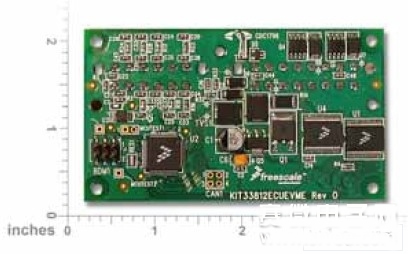
Figure 6 MCZ33812 reference design board
It is based on the MCZ33812 and MC9S12P128 16-bit MCUs and has 128 Kb of flash memory. It is a complete ECU whose design represents the use case of the MCZ33812 in practical applications for single-cylinder, 4-stroke engines; due to the basic feature set of the MCZ33812, some other analog functions are also implemented using separate components. The board also features a stepper motor driver for idle management, a VRS air conditioning circuit and an oxygen sensing heating driver. With this hardware, some examples of software code and device drivers are also available.
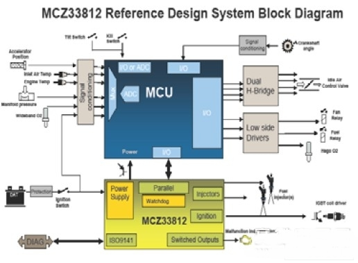
Figure 5 MCZ33812 reference design block diagram
The reference design connector provides the following signals:
input signal:
1. VSRP - Variable Reluctance Sensor (Positive)
2. VRSN - Variable Reluctance Sensor (Negative)
3. MAP - Intake manifold pressure sensor
4. TPS - Throttle Position Sensor
5. ATEMP - External Temperature Sensor
6. ETEMP - Engine Temperature Sensor
7. O2IN - oxygen sensor
8. OPSR - Oil pressure sensor
9. ENGSTOP - engine disconnect switch
10. TILTSW - Signal indicating the engine's safe direction of operation
output signal:
1. TPMD - Throttle position stepper motor output D
2. TPMC - Throttle position stepper motor output C
3. TPMB - Throttle position stepper motor output B
4. TPMA - Throttle position stepper motor output A
5. INJOUT - Injector LS drive output
6. COIL - Ignition Coil LS Drive Output
7. +5V - power output voltage
8. LAMPOUT - Fault indicator LS drive output
9. ROUT1 - Relay LS Drive Output 1
10. ROUT2 - Relay LS Drive Output 2
11. O2HOUT - Oxygen sensing heater LS drive output
The remaining connections include:
1. VBAT - 12 V battery positive input
2. GND - 12 V battery negative input
3. ISO9141 - Diagnostic Input/Output
4. GND - 4 other ground connections
The Reference Design Toolbox contains boards with cables and connectors, including BDM programming modules, DVDs with Code warrior development software, and examples of real-world working software with complete source code and documentation (which can be used to run small engines). The reference design also includes the actual operation of a single or twin-cylinder engine, as well as everything else needed to develop an engine “calibration†table that increases efficiency and reduces emissions.
summary
The era of small gasoline engines switching from mechanical control to electronic control has arrived. Legislation on reducing pollution and improving efficacy has already begun in countries.
In order to reduce the size of the ECU and reduce costs, most of the individual components must be integrated. Freescale's first ASSP product brings a large number of analog functions to a single chip, leading the market again. In addition, it provides a reference design that provides ECU designers with a critical first step in the learning curve to help them meet new regulatory requirements and make small gasoline engines more “greenâ€.
Outdoor Speakers,Outdoor Speaker System,Outdoor Bluetooth Speakers,Outdoor Wall Mounted Bluetooth Speakers
The ASI Audio technology Co. LTD , https://www.asi-sound.com