
In computing and consumer electronics, efficiency has improved significantly, with a focus on AC/DC conversion. However, with the advent of 80 PLUS, Climate Savers and EnergyStar 5, designers are beginning to realize that both AC/DC and DC/DC power systems need to be improved.
This article refers to the address: http://
The average AC/DC system efficiency is around 65%, while the DC/DC average system efficiency is 80%, so it's not hard to understand why everyone focuses on AC/DC systems. However, it is time to re-examine the DC/DC system to find new ways to improve efficiency.
DC/DC in computing, communications, and consumer applications is responsible for converting, managing, and distributing power, providing power to functions such as graphics cards, processor chips, and memory, all of which face increased performance requirements, so more than ever All need more efficiency. Research has been conducted on the latest advances in MOSFETs and advanced thermal packaging techniques to increase the efficiency of existing switching circuits and associated power transistor devices.
Careful selection of power components, especially on-board synchronous buck converters, can significantly improve the power density, efficiency and thermal performance of the new platform. For example, if 500,000 servers are fully compliant with the 80 PLUS energy regulations, the energy savings are sufficient to supply more than 377,000 homes.
Circuit and loss
The buck or synchronous buck circuit is a heavy-duty component of all low-voltage DC/DC power management systems, and the main power loss in all synchronous buck circuits comes from the switching and conduction losses of the MOSFET.
A common step-down rectifier (VRM) can be found in any desktop computer, as shown in Figure 1, which provides more than 25A of current and 1.2V of output at full load. Therefore, one MOSFET will be in the main or high side slot, and two parallel MOSFETs will be in the flywheel or bottom slot. The 12V input is stepped down to a 1.2V output, then the duty cycle is 10%, so the high-side MOSFET will regulate to low switching losses, while the low-side MOSFET pair will minimize RDS(ON) to minimize conduction losses. .
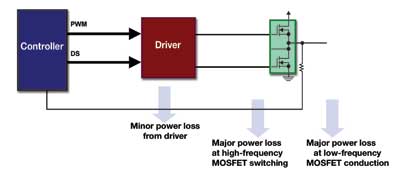
Figure 1 Common voltage rectifiers in desktop computers
The typical peak efficiency of a multiphase VRM VCORE scheme implemented by discrete drivers and MOSFETs is 90%, occurring at 10A per phase of rated current, while at full load of 30A, efficiency is reduced to 85%. For today's designers, a complete VRM system typically has an output of 100W and an efficiency of 85%, which means a power loss of 15W.
Step-by-step improvement of silicon-based MOSFETs
MOSFET manufacturers mainly optimize the process in two ways. First, in order to improve the switching characteristics (switching speed) of the products, they implemented an advanced gate structure design that reduced the gate charge (Qg) effect. The second is to increase the cell density, that is, the on-resistance is significantly reduced on wafers of the same size. RDS(ON) and current are two determinants of MOSFET conduction loss. The calculation formula for conduction loss is simple:
Ploss=I2×RDS(ON) conduction loss
Ploss=1/2V×I×(Tr+Tf)×F Switching Loss
Figure 2 shows an improvement in Fairchild's ≤30V N-channel MOSFET cell density. Each bar represents a new process advancement. It can be seen that in the last decade, the cell density has increased from 32 million units per square inch to the current 1 billion units per square inch.
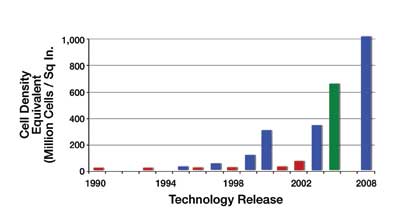
Figure 2: Advances in cell density in N-channel MOSFETs smaller than 30V
MOSFET performance factor
In the industry, the commonly used performance measurement method is always the coefficient of performance (FOM), and fundamentally, this is only a comprehensive consideration of the transistor on-resistance and gate charge.
FOM=RDS(ON)×Qg
RDS(ON) is directly related to conduction loss, while Qg is directly related to switching losses. The smaller the FOM, the better the performance.
Figure 3 shows the progress of FOM in the development of low voltage MOSFET processes. For the PowerTrench3 implemented in 2004, the best FOM is 240, and the best FOM in today's PowerTrench5 silicon process is 126.
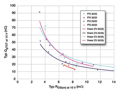
Figure 3: Improvements in the performance factor (FOM) of low-voltage MOSFETs
Unfortunately, a 50% reduction in FOM does not mean a 50% reduction in MOSFET losses because their relationship is not linear. However, with careful selection and optimization, today's MOSFETs can still significantly reduce the power loss of the system.
System level efficiency
Therefore, the power MOSFET is the main culprit in the power loss in the DC/DC power circuit, and this loss can be greatly reduced by using advanced devices. So what is the relationship between this and the overall efficiency of the system?
Designers seek ways to improve system efficiency over the entire machine's operating range when the load is low, medium, and high, respectively. At full load, such as when the computer is started or the processing is busy, conduction losses dominate the power system. Simply select a MOSFET with a smaller RDS(ON) to significantly reduce losses. Interestingly enough, most PCs are in standby or sleep most of the life of the work, so efficiency at low loads is very important.
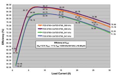
Figure 4 VR11.1 (Intel motherboard power supply specification) VCORE tube efficiency comparison
Figure 4 shows the actual efficiency plot, taken from the desktop power rectifier module phase column. These four curves are the result of two different MOSFET devices at 300 kHz and 550 kHz, respectively. We can see the efficiency over the entire load current range.
Note the two curves above. At full load (30A), you can see a 1.5% improvement in the efficiency of the latest devices. The same is true for the two curves. When the load is small (15A), an improvement of 0.69% can be achieved. If the entire load range is integrated, the average power loss can be reduced by 8% to 10% when using the latest MOSFET devices compared to today's common solutions. Even at the higher switching frequency of 541 kHz, it can be seen that system efficiency is still higher than 80% at load hours and greater than 70% at full load. If the frequency continues to increase, the switching losses will increase dramatically.
The optimum operating frequency of most DC/DC converters is 250 to 300 kHz because the switching losses and conduction losses generated by such frequencies are affordable and the ripple output to the load is low enough. The efficiency is higher when operating below 250 kHz, but the voltage output may be too small to be used to power the Pentium chipset.
The same idea can be used for laptop processor power supplies, gaming consoles, and in set-top boxes and other consumer electronics, although their currents are much smaller. Every milliwatt of energy savings seems to be difficult. However, it can make a global improvement for today's environmental problems. Small improvements in many methods have a significant effect.
About Silicone Sanitizer Sleeve :
Most people like to bring a bottle of sanitizer when they go hiking ,go climbing.Sanitizer is very useful when we get dirt on the hands,and very convenient to carry ,while as it's liquid in the bottle ,sometimes it overflows ,it's not good to put into the bag ,and also not convenient to hold on hand .How to solve these problems ,well,our factory can help you to do your customized Silicone Bottle Holder to hold the bottle very well ,and you can tie it on your bag ,it's very convenient for carrying and using ,come on !
Welcome to visit our Hand Sanitizer Holder such as Sanitizer Bottle Silicone Holders,Hand Sanitizer Silicone Holder,Silicone Hand Sanitizer Holder, Silicone Sanitizer Holder
Silicone Sanitizer Sleeve description:
1.Product name:Hand Sanitizer with Silicone Holder,Hand Sanitizer Holder,Sanitizer Bottle Silicone Holders,Hand Sanitizer Silicone Holder,Silicone Hand Sanitizer Holder,Silicone Sanitizer Holder
2.Place of origin:Guangdong China
3.Color:any pantone color
4.Logo:printing,debossed,embossed
5.MOQ:500pcs.
6.Package:1 pcs/opp,customized design is available.
7.Design:Customized
8.Certification:FDA,LFGB,SGS,ROHS,etc.
9.Usage:sanitizer bottle protector
10. Silicone Bottle Sleeve photos for reference

Silicone Sanitizer Sleeve
Silicone Sanitizer Sleeve,Hand Sanitizer with Silicone Holder,Hand Sanitizer Holder,Sanitizer Bottle Silicone Holders,Hand Sanitizer Silicone Holder,Silicone Hand Sanitizer Holder,Silicone Sanitizer Holder
OK Silicone Gift Co., Ltd. , https://www.oemsiliconegift.com