
I am here to test and demonstrate the proportional power operation of the combination of PRM and VTM. I will use these evaluation boards to test.
This article refers to the address: http://
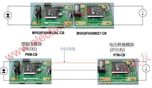
The two boards can be joined to form a complete DC-DC converter function. On the other hand, VTM can be seen as a point-of-load device, which puts the current multiplication and voltage residual functions at the point of load and is isolated. The PRM of the upper stage acts as a non-isolated voltage regulator, and the control divides the bus to the VTM to achieve the output regulation. The voltage of the sub-bus is relatively high, so the PRM can be placed away from the load point. Where, this means that valuable load point space can be vacated and left for use by other more important functions.
Before the test, the data sheet of each device and the use guide of the evaluation board should be prepared so that they can be read at any time when necessary.
We will mainly demonstrate the operation of the adaptive loop mode. We will see that this PRM-VTM combination provides tight regulation without the need for real-time remote sensing.
In this mode, PRM can control the proportional voltage of the busbar Vf to reach the load point Vo.
This is the case with the device being tested. Here we try to divide the two boards apart, and only use the twisted pair of light wire to transmit the power of the split line.
Input change, proportional bus voltage regulation (Vf)
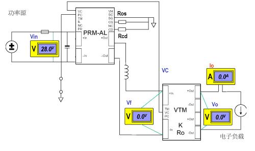
PRM provides a lot of flexibility, allowing us to set its operating mode and other parameters, and only need to use simple peripheral resistors. We can also see the open-loop operation mode of PRM here. In this open-loop mode, PRM will stabilize the sub-ratio to the ground.
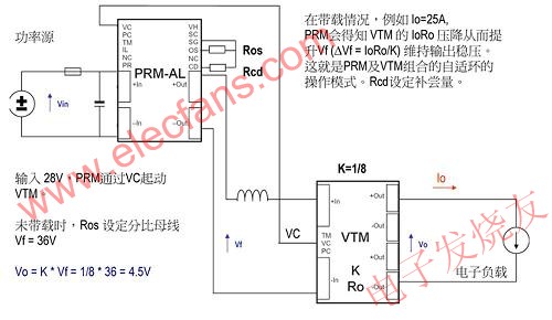
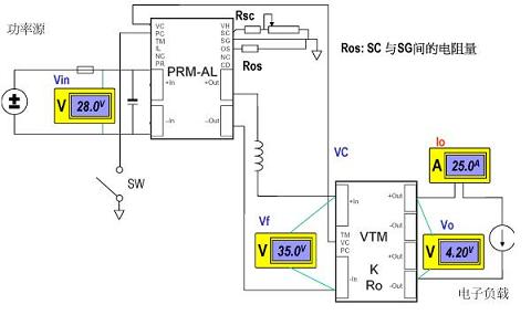
Now suppose that Vf is set to 36V. This can be done with the appropriate Ros. The voltage on the bus will be constantly regulated, and the voltage is regulated throughout the input range. The input range of our PRM is 16V to 50V. Regardless of the input operation at any point from 16V to 50V, the split bus is always regulated at 36V.
Use Ros to set the split bus voltage (Vf)
Just set the split bus to 36V. In fact, you can set any operation point between 26V and 50V. Just select Ros. The potentiometer on the evaluation board can easily set the desired ratio. Bus voltage, which actually means the voltage of the load point to be set, because the input and output of VTM are linear ratio, which is the fixed input and output ratio, called K factor.
Increasing Ros will increase Vf (26-50V)
Use Vsc to downgrade Vf
Once the sub-ratio voltage is set, or the output point voltage is set equally, the output voltage can be changed using the SC. This is another useful flexibility. On the evaluation board, a potentiometer is available. To fine tune the sub-bus or load voltage. The transfer function from SC to Vf has a fairly high bandwidth, and many useful applications can be developed through it.
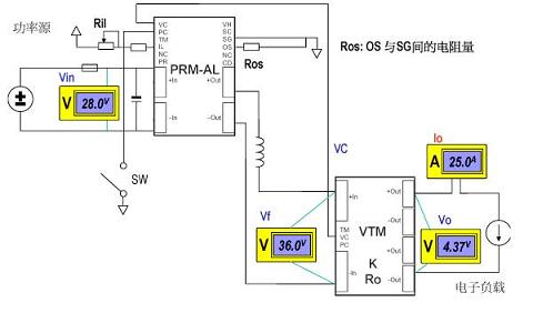
PRM preset current limit can be adjusted by IL terminal
Another flexibility of PRM is that it can lower its preset current limit point. It can be obtained with a resistor of appropriate resistance and fine-tuned at IL. It is worth noting that the lower VTM may also have its own current limit setting. It is usually better to let the PRM replace the VTM's current limiting effect, so it is necessary to move the PRM current limit set point if its preset point is higher than VTM.
Open loop mode - Vf regulator
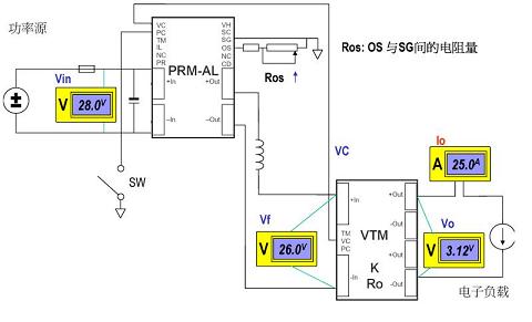
Now let's assume that the set ratio is 36V, and then change the load current to see its operation. The split bus is regulated, and the load voltage is also regulated. For many applications, it is enough. Its voltage regulation rate is about 5%. Can it be further improved? Of course, in fact, now PRM is only operating in open-loop mode, only the sub-ratio is regulated, PRM is more commonly used in another mode called adaptive loop mode, we are very I will see how it is.
Now it is still open-loop mode, the ratio bus is tighter to ground, and the load voltage will drop at high current. This is because the VTM output has internal resistance. But the internal resistance is very small, only a few mΩ. The magnitude of the VTM used in our tests has an internal resistance of approximately 5.1 mΩ.
Vo will be regulated under the adaptive loop
To do a good job in starting the adaptive loop is to add a compensation device, just add a resistor on the CD side; the amount of resistance must be determined according to what VTM is applied, can be found from the table of the data sheet, or calculated by the formula , also found in the data sheet.
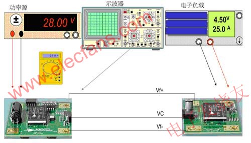
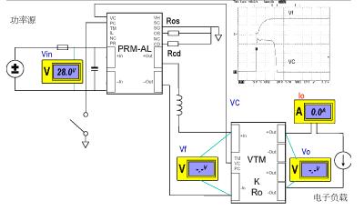
Now we start testing, the 28V input is ready, and we still see no output, because we have not yet started that PRM.
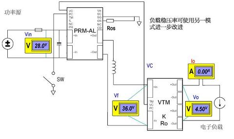
We set the load current first to 0A, then release the PC side of the PRM to start it.
Enable PRM activation via PC
Startup; The split bus Vf is rising, and the next event is that the PRM sends a start VC pulse to start the VTM. This is seen by the oscilloscope.
The instrument at the output, because it is a slow response measurement tool, has not been able to determine the output value in the output setup change.
The output is now set and is 4.5V, which is the expected number.
We will increase the load current, look at the load point of the VTM output, what is the voltage regulation?
Increase load current
The load current is now 5A. Vo is tight to regulation.
Higher load current, 10A. We seem to be getting very good load regulation, why?
Note that the split bus voltage is being controlled by the PRM.
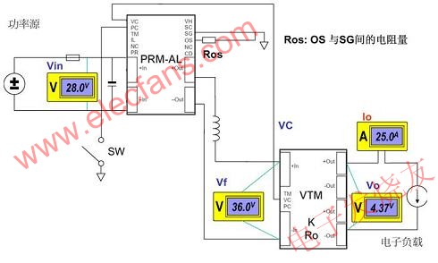
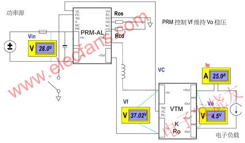
Increase load current (25A)
Now it is overloaded, the load regulation is excellent, the reason is that PRM can control the split ratio bus, which is controlled according to the feedback current information. In this way, the voltage drop of the output internal resistance is compensated, and the output is stabilized. When pressed, it should also be noted that the voltage at the load point is controlled and regulated without remote sensing voltage sampling. The working mode of the PRM-VTM combination is called the adaptive loop mode.
Xunda the fashionable change of family kitchen very well.closely related to the common people's life.Adopting the latest and contemporary concepts,design and make the new generation super strong suction Range Hoods,with lower noise, non-stick oil,easy clean,refined&elegant appearance,bring us [attractions",so great deal of niceness,be of the best choice for your perfect and quality life.

Downdraft Cooker Hood,Range Hoods,Kitchen Hood,Ceiling Built In Hood
Xunda Science & Technology Group Co.ltd , http://www.xundatec.com