
1 Introduction
This article refers to the address: http://
The Automotive Engine Control Module (PCM) is the vehicle's control nerve center that directly affects the car's power and fuel economy and exhaust emissions. With the development of the automotive electronics industry, PCM has become a standard configuration for automobiles. Due to the complexity of the PCM system and the extremely harsh working environment, its reliability is of paramount importance. Therefore, the PCM durability test is an important supporting condition for the development of automotive engine PCM.
In the 1980s, several well-known international PCM module manufacturing companies, such as Bosch, Siemens, Delphi, and Visteon, conducted research on PCM durability testing technology for their own products and developed corresponding equipment. Because this kind of equipment still uses the design system more than 20 years ago, it can not adapt to the development of the ever-changing automotive EFI engine technology. The overall technology platform is backward, and there are some insurmountable defects, such as not being compatible with PCM modules of different manufacturers. Set the automatic cycle strategy, and you can't configure analog signal types and parameters on the spot. At present, China's self-developed automotive electronic products are in an accelerated development stage, but due to the late start of China's automobile industry, its own technology is backward, and its scientific research capability is not strong [1]. The existing PCM technology comes from abroad, and the durability test of PCM is concerned. Technology is still a blank in China. Only a few colleges and universities have carried out research on fault diagnosis, signal testing, and running machine simulation around the automobile EFI engine [2 - 4], and no complete set of technology has been formed.
This paper introduces the overall design ideas and test specifications of the automotive PCM durability test system, focuses on the design principles of the key subsystems, and tests the long-term reliability of several PCM modules through prototypes, verifying the reliability and versatility of the system. .
2, the overall concept
2.1 PCM working principle
The automobile engine control module (PCM) is the core component of the vehicle control system. It is mainly composed of five parts: input circuit, analog signal, digital signal converter, microcomputer and output circuit. Its function is to receive various sensor signals, and to issue instructions to the actuator through the operation and processing of the microcomputer, turn on the grounding wire of each actuator, and make it work energized to accurately control the fuel supply amount, the ignition advance angle and the idle air. flow.
2.2 PCM durability test system design ideas
Based on the control technology of EFI engine, this paper designs a universal open PCM durability test system by using multi-layer CAN bus communication technology, virtual instrument technology and embedded computer system. It mainly consists of industrial control computer (IPC), signal generation subsystem, analog load subsystem, load monitoring subsystem, high-power program-controlled power supply, environmental experiment box, fieldbus communication subsystem, application software and database management system. Its hardware system and prototype are shown in Figure 1 and 2.
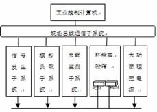
Figure 1 Hardware system of PCM durability test common platform
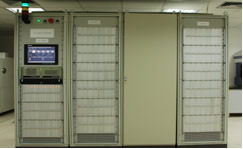
Figure 2 Prototype of the PCM durability test system
The test principle of the test system: PCM is the test object, the industrial computer sends setting instructions according to the test type and test items, controls the environmental variables and high-power DC power supply, quickly switches the vehicle sensor signal and the analog load connection, and promptly The load monitoring system sends a read command to monitor the PCM operating status online.
2.3 PCM Durability Test Specification
The durability test specification is the basis for the PCM durability test and is related to the overall quality of the PCM. In order to improve the reliability and durability of the PCM during normal operation, it is necessary to establish a test specification that can maximize the PCM failure. The system establishes the principles of durability test specifications: (1) fully consider the various stress parameters that cause PCM failure; (2) ensure sufficient test time to verify that the PCM module has sufficient reliability over the expected lifetime [5].
According to the extreme environment under various working conditions of PCM, important parameters such as temperature, humidity and power supply voltage were determined, and a set of test specifications with a period of 6 hours was established, as shown in Figure 3, and the DSPACE rapid development platform was adopted. Inspection of the durability test experimental platform established with the NI virtual instrument platform.
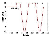
(a) Temperature and humidity parameters
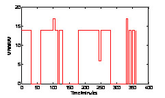
(b) Power parameters
Figure 3 Test specifications for related parameters
3. The main structure of the PCM durability test system
This system adopts Advantech industrial computer, installs Visual C++, LabVIEW and other development application software by inserting conditioning amplifier, A/D, D/A card, and forms a virtual instrument platform, which realizes the digital digital acquisition test analysis of the computer. In addition, the system selected the Agilent 6691A high-power programmable power supply for simulating battery and generator operation, and designed an environmental test chamber capable of accommodating multiple PCMs.
3.1 Signal Generation Subsystem
In the related literature, the signal generating devices are designed only for a specific PCM, and the flexibility is poor. The subsystem utilizes virtual instrument technology, and the main structure is an embedded computer system with ARM microcontroller and CPLD as the hardware framework. As long as it is assigned to different identification (ID) of each signal generation module, it can be extended by the field bus to realize the multi-module signal generation subsystem network.
The use of DDS technology is a mainstream practice in the current test and measurement industry [6], and its frequency accuracy can be determined by the number of bits of the phase accumulator. The system uses a single-chip + dedicated DDS chip to generate a sinusoidal signal. The principle is shown in Figure 4. The ARM microcontroller sends a control command to the CPLD. After the CPLD decodes the clock, it generates a DDS control signal to generate a sine wave of the corresponding frequency. The signal, after being filtered and amplified, outputs a sinusoidal signal of a corresponding amplitude.
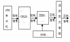
Figure 4 Schematic diagram of sinusoidal signal generation
The crankshaft position signal (CPS) is the most important sensor signal in the PCM control ignition system. In order to meet the needs of various PCMs, the design is generated by CPLD and DA. The principle of CPS signal generation is shown in Figure 5. There is a period of sine table data in the EPROM. When the CPS signal needs to be generated, the ARM MCU sets the CPLD. The CPLD generates a read memory by clock counting according to the received control command. The signal, and provide the appropriate address signal and control signal to the EPROM, EPROM output the corresponding address data, D/A conversion, into a single-ended CPS analog signal, and then through the filter circuit and single-ended to differential processing circuit, output CPS Differential signal. In the actual circuit implementation, the control of the CPS signal can be set by the computer to the ARM via the CAN bus. Therefore, even if the ARM chip is reset during operation, the circuit can still output the correct CPS signal to ensure the test cycle. Work properly.
The subsystem also designed two kinds of VREF/2 signal generation methods for the requirements of various PCM modules: resistance voltage division method and operational amplifier voltage division; meanwhile, PWM generator is designed by using 555 time base circuit and filter amplification circuit. In addition, the subsystem uses a resistor divider and integrated op amp isolation to generate a small amplitude fixed voltage signal (such as 1.0V) required by the PCM.
3.2 Analog load subsystem 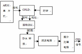
Figure 5 CPS signal generation schematic
The subsystem mainly simulates the output load of the PCM-connected ignition coil, fuel injection, canister solenoid valve, and exhaust gas recirculation. The subsystem is an open load system that simulates various PCM output loads and can be extended by fieldbus.
This paper comprehensively analyzes the commonality and particularity of PCM loads, and designs two types of load boards: common load boards and special load boards. The analog load module consists of multiple analog load boards and is placed in the load box together with the load monitoring module. When a specific project test is required, the load switching can be done through the relay matrix. In addition, photoelectric isolation is used to convert the PCM output signal into a +5V TTL signal that the load monitoring subsystem can receive.
3.3 Load Monitoring Subsystem
The subsystem is also an embedded computer system based on ARM microcontroller and CPLD as the main hardware framework, and can be extended by the field bus. The subsystem reads the monitoring signal in the analog load subsystem in real time, and monitors the changes of all load signals output by the PCM during the durability test, including the signal change period, the timing of some important signal outputs, etc., and the monitoring results. , uploaded to the industrial computer through the field bus.
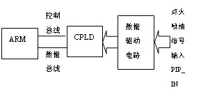
Figure 6 ignition and fuel injection signal monitoring principle
Ignition and fuel injection signals are key signals in automotive engines. The cycle and timing are directly related to the operating state of the vehicle, so monitoring their cycle and timing is especially important. The monitoring principle diagram of this system is shown in Figure 6. For the monitoring of the ignition signal, it mainly monitors the synchronization with the CPS signal and the timing relationship between two or four ignition signals. After the CPLD finds the starting point of the ignition signal synchronized with the CPS, each ignition signal is counted according to the input PIP_IN signal. Whenever an ignition cycle is completed, an interrupt signal is generated to the ARM microcontroller during the next ignition cycle. The interrupt signal triggers the ARM microcontroller to enter an interrupt processing program. In the interrupt program, the ARM microcontroller reads the count value of each ignition signal, determines the timing and period of the ignition signal, and sets a flag indicating whether the ignition signal is normal or not. For the monitoring of the fuel injection signal, it is mainly to monitor its synchronization with the CPS signal and the timing relationship between them. When the falling edge of any of the four injection signals in the PIP_IN signal arrives, the CPLD will monitor the status of the other three injection signals. If the status of the other three injection signals is normal, the normal signal of the injection signal is given. On the contrary, the fuel injection signal abnormality flag is given.
For slow signals with low frequency changes (such as 2 Hz) in the PCM module, the system uses RS232 bus read mode to monitor their periodic changes by ARM.
3.4 Fieldbus Communication Subsystem
Since a large amount of data needs to be transmitted between two subsystems of the whole system, high requirements are placed on the communication of the system: on the one hand, there is a higher communication rate; on the other hand, there is a more flexible protocol conversion. . Due to its outstanding reliability, real-time and flexibility, the CAN bus has been widely recognized and used in the industry [7]. The system adopts the fieldbus communication subsystem which is mainly based on CAN bus and has K-LINE, GPIB, RS485 and 245 bus, and can flexibly form multiple communication subnets to complete the requirements of multi-module testing. The system uses two CAN subnets (CAN0, CAN1). For each PCM, the signal generation module and the load monitoring module and the PCM form a communication subnet CAN 1. The IPC connects the subnets together via the communication subnet CAN0.
CAN communication between signal generation subsystem and industrial computer: (1) Set signal generation module, its setting range is mainly CPS type, start CPS, start sinusoidal signal generation and switch input relay; (2) control and read PCM fault Code. The signal generation module is a transfer station for the industrial computer to communicate with the PCM. When the industrial computer sets the PCM or reads the fault information of the PCM module during operation, it first sends an instruction to the signal generation module through CAN0. After receiving the instruction, the signal generation module only changes the ID and sends it to the PCM module through CAN1. Similarly, after receiving the CAN message returned by the PCM, the signal generation module only sends the ID to the IPC through CAN0. Considering the difference in communication interfaces of different PCM types, a KLIN bus is added between the signal generation module and the PCM. When the PCM or the PCM fault code is to be set, the signal generation module receives the command through CAN0, converts it into a KLIN message, and sends it to the PCM module. Similarly, the KLIN message returned from the PCM is converted by the signal generation board into The CAN message is returned to the industrial computer through CAN0.
CAN communication between the load monitoring subsystem and the industrial computer: (1) Set the relay matrix. The industrial computer sends an instruction to set the relay matrix to the load monitoring module. After receiving the instruction, the load monitoring module transmits the relay matrix information to the corresponding analog load module; and (2) reads the load monitoring information. When the system works, the industrial computer continuously sends an instruction to query the load monitoring information to the load monitoring module. After receiving the instruction, the load monitoring module sends the current PCM load monitoring data into a CAN message and sends it to the industrial computer.
In addition, the analog load subsystem is connected to the load monitoring subsystem through the RS245 bus, and transmits the relay matrix information to each analog load module to complete the load switching work; the high-power programmable power supply is connected to the industrial computer through GBIP, and receives the power setting of the industrial computer. The environmental test chamber is connected to the industrial computer through RS485, and receives its setting commands to adjust the ambient temperature and humidity.
4 Conclusion
At present, the system has been successfully used in PCM, STC 1×× and 2×× series PCM durability tests of Changan CB series, which verifies the versatility and reliability of the system. Since the motorcycle's PCM is similar to the car's PCM principle, it is also suitable for motorcycle PCM durability testing. Although the system may still have some shortcomings, it will provide solid equipment support for the development of automotive engine control systems through continuous improvement and upgrade.
Fiber Patch Cord is a length of optical cable with connectors fixed on two ends to realize the optical path active connection.If both sides of the connector or its end-face are different, it is called hybrid Fiber Optic Patch Cables.Main types of Optical Patch Cord are SC Patch Cord , LC Patch Cord , FC Patch Cord , ST Patch Cord , Multimode Fiber Patch Cord,Single Mode Fiber Patch Cord, Duplex Patch Cord , Simplex Patch Cord . In order to assure of high performance,they are made with CCTC brand`s premium grade connectors.Meanwhile,Fiber Optic Patch Cord is also available with different colors,diameter and jacket types, which can be made to any length to fit FTTH projects. Fiber Patch Cables are not only widely used for communication rooms,FTTH,LAN,fiber communication systems,fiber optic transmission equipment and other telecom fields,but also they are applicable to cable television networks, telecommunications networks, computer optical network and optical test equipment. Foclink,a reliable supplier of fiber patch cord is always beside u 7*24.
Fiber Patch Cord
Fiber Optic Patch Cord,Optical Patch Cord,Fiber Patch Cables,Fiber Optic Patch Cables
Foclink Co., Ltd , http://www.scfiberpigtail.com