Many people who have a basic understanding of analog-to-digital converters (ADCs) often ask how to convert ADC codes into actual voltage values. Or, in specific applications, they may want to translate the ADC code back into physical quantities like current, temperature, weight, or pressure. In this two-part blog series, I will walk you through the process of converting ADC codes into voltages and then into real-world measurements. In the first article, I’ll focus on the fundamentals of converting an ADC code back to its corresponding voltage. In the second part, I’ll provide practical examples showing how to calculate physical parameters from the measured voltage.
**Converting Code to Voltage**
An ADC takes an analog signal and converts it into a digital code that represents the sampled input. This digital output is processed and used by the system for further analysis or decision-making. Therefore, accurately mapping the digital code to the original analog signal is crucial for reliable data interpretation.
The relationship between the input voltage and the ADC output code is typically linear and can be described by Equation 1:
$$ V_{IN} = \text{Code} \times \text{LSB size} $$
Where $ V_{IN} $ is the input voltage, "Code" is the decimal value of the ADC’s digital output, and "LSB size" is the value of the least significant bit in the ADC's output.
This equation applies to all types of ADCs, whether the output is in binary or two’s complement format, as long as the binary value is correctly converted to its decimal equivalent.
**Determining the LSB Size**
Once the ADC conversion is complete, the input voltage can be calculated by multiplying the decimal value of the output code by the LSB size. Understanding the LSB size is essential when translating between digital codes and actual voltages.
Equation 2 defines the LSB size:
$$ \text{LSB size} = \frac{\text{FSR}}{2^N} $$
Where FSR is the full-scale input range (in volts), and N is the number of bits in the ADC’s output code. The total number of possible codes is $ 2^N $, so the LSB size is essentially the step size between each code over the entire input range.
For example, a 4-bit ADC has 16 codes ($ 2^4 = 16 $), and the input voltage is divided into 16 equal steps. Figure 1 illustrates this step function for a 4-bit ADC.
**Full-Scale Range and Reference Voltage**
It’s important to know the FSR of your ADC because different devices have different ranges. The FSR is proportional to the reference voltage and may also depend on internal gain settings. Equation 3 shows how the FSR relates to the reference voltage:
$$ \text{FSR} = m \times V_{REF} \times \text{Gain} $$
Where $ V_{REF} $ is the ADC’s reference voltage, m is a scaling factor based on the input range (e.g., 2 if the input spans from -VREF to +VREF), and Gain accounts for any internal amplification before the ADC.
In delta-sigma ADCs, for instance, a programmable gain amplifier (PGA) is often included before the ADC. By incorporating the PGA gain into the FSR calculation, the LSB size automatically accounts for this amplification. This ensures that when you multiply the code by the LSB size, you get the actual input voltage before any amplification, not the amplified output.
**Sample Code**
Most microcontrollers read ADC data in 8-bit chunks and combine them into a larger data type, such as a 32-bit integer. If the ADC has a resolution less than 32 bits and uses signed output, you must sign-extend the result to preserve the correct value. The code in Figure 3 demonstrates how to handle a 24-bit ADC output.
Now that you understand how to convert ADC codes into voltages, the next step is to explore how these voltages relate to real-world physical parameters. In the next part of this series, I’ll show you how to use this information in practical applications.
Ribbon Cable Connectors
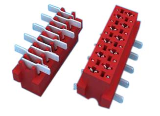
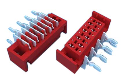
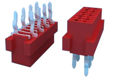
1.ANTENK Insulation Displacement termination connectors are designed to quickly and effectively terminate Flat Cable in a wide variety of applications. The IDC termination style has migrated and been implemented into a wide range of connector styles because of its reliability and ease of use. Click on the appropriate sub section below depending on connector or application of choice.
2.Our products are widely used in electronic equipments,such as monitors ,electronic instruments,computer motherboards,program-controlled switchboards,LED,digital cameras,MP4 players,a variety of removable storage disks,cordless telephones,walkie-talkies,mobile phones,digital home appliances and electronic toys,high-speed train,aviation,communication station,Military and so on


SPECIFICATION
Current Rating: 1.0Amp
Insulation Resistance: 1000MΩ min
Contact Resistance: 20mΩ max
Withstand Voltage: 500V AC/DC
Operating Temperature: -40°C to +105°C
Contact Material: Phosphor Bronze
Contact Plating: Au Over Ni
Insulator Material: High Temperature plastic UL94V-0
Ribbon Cable Connectors,Cable Connector,Cable Assembly,Connector Flat Ribbon Cable,Box Header Connector,Latch Header Connector,IDC Socket Connector,Dip Plug Connector
ShenZhen Antenk Electronics Co,Ltd , https://www.antenk.com


