
The input voltage range is from 0.9V to 5.5V, making it suitable for a wide range of low-voltage applications.
The output can be set to either 5V or 3.3V, or it can be adjusted between 2V and 5.5V, offering flexibility for different power requirements.
This DC-DC converter achieves up to 94% efficiency at a 5V output, ensuring minimal power loss and high performance.
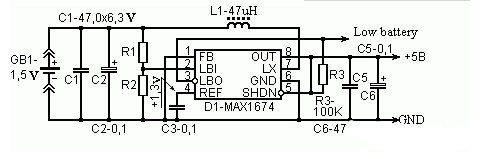
Figure 1: 1.5V to 5V Boost Circuit Using MAX1674
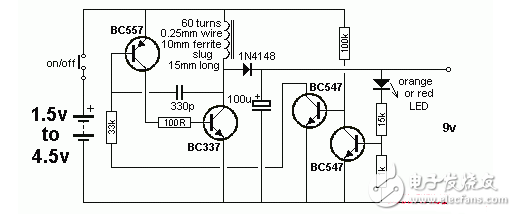
**Booster 1.5V to 5V Circuit Diagram (2)**When supplying power to a 2.5V to 3.0V circuit, the efficiency reaches approximately 70% with an output current of 20mA, which is ideal for low-power devices.
This circuit provides a 1.5V to 9V power supply using a switching boost configuration. BG1, along with L1, L2, and C1, forms an oscillator that generates the necessary high-frequency signal.
BG1 acts as a switching transistor, operating in a continuous oscillation mode. L1 and C1 are used for feedback, while L2 serves as the energy storage winding. To simplify the design, an automatic electronic switch composed of BG3 is included.
When no load is connected to points A and B, BG3 remains off, preventing current flow through BG2 and BG1, effectively turning off the circuit. This eliminates the need for a separate power switch, saving space and reducing complexity.
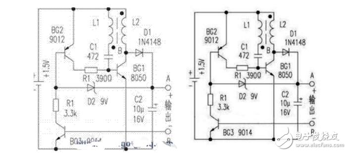
When a load is connected to A and B, BG3 turns on, activating BG2, which then supplies base current to BG1. As BG1 turns on, energy is stored in L2. During this time, D1 is reverse-biased, and the load draws power from C2.
When BG1 turns off, the sudden change in current through L2 induces a higher counter-electromotive force (EMF), which is rectified by D1 and delivered to the output. If the output voltage exceeds the regulation value set by D2, BG2 begins to conduct, reducing the base current of BG1 and thus lowering the output voltage until it stabilizes near the desired level.
**Component Selection and Production Debugging:**For BG1, choose NPN silicon transistors with low saturation voltage, such as 9013 or 8050, ensuring ICM ≥ 300mA and β ≥ 200. BG2 can be a PNP transistor like 9012 or 9015, while BG3 should be an NPN type like 9014. Lower leakage current is preferable for better performance.
Winding L1 and L2 on a 8mm high-frequency ferrite ring (recovered from an old electronic ballast or energy-saving lamp) using 0.1mm enameled wire is recommended. L1 has 6 turns, and L2 has 36 turns.
I tested this circuit to power a DT890A digital multimeter. The measured working current was below 45mA for the buzzer and capacitor block, and under 25mA for other settings. When the battery voltage dropped to 0.9V, only the buzzer block showed a low-voltage warning, while the rest of the functions remained stable.
This circuit is simple to build, reliable, and cost-effective. No complex tuning is required—just correct wiring will make it work efficiently. It’s especially useful for replacing 9V batteries with 1.5V ones in digital multimeters, eliminating the need for a separate power switch. Instead, the circuit activates automatically when the meter draws current, making it more convenient for both production and daily use.
480W Medical Power Supply,480W Medical Device Power Supply,480W Medical Power Adapter,480W Rade Power Supplies
Shenzhen Longxc Power Supply Co., Ltd , https://www.longxcpower.com