
People need high-efficiency, low-power, energy-efficient electronic devices that require higher-performance, smaller form factor wireless systems, which are a huge battle for power and power management design. Designers need to provide multiple voltages, more current, higher efficiency, lower power, lower noise, smaller form factor power and power management for a variety of DSPs, MCUs, FPGAs, ASICs, audio/video and display circuits . A variety of power architectures have emerged to meet changing power management requirements.
Distributed power architecture
The Distributed Power Architecture (PDA) is the first generation power architecture for base stations. An example of a PDA is shown in Figure 1. This power architecture is provided for each voltage rail with an isolated (brick) power module. When the voltage rail is limited, the PDA works well, but for every additional voltage rail, its cost and PCB area increase significantly. Voltage rail timing is also difficult, and external circuitry needs to be added to address voltage rail timing, which also increases cost and board area.
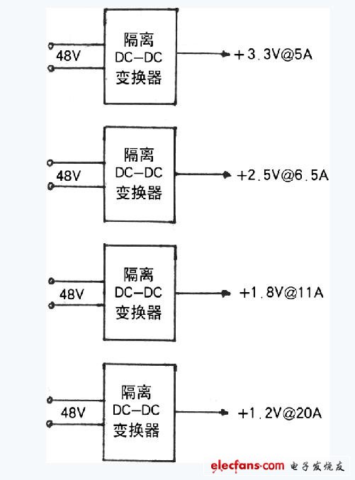
Figure 1 Typical DPA architecture
Intermediate bus architecture
In order to overcome the shortcomings of large DPA size and high cost, the second generation system adopts the Intermediate Bus Architecture (IBA) architecture. The intermediate bus architecture has several fixed-voltage IBAs, unregulated IBAs, and Quasi-regulated IBAs. The fixed voltage IBA shown in Figure 2 uses a single isolated brick power module and many non-isolated point-of-load (Pol) DC/DC converters. Pol can be a power module (such as TI's PTH series) or a discrete buck converter. The input voltage range (36~75V or 18~36V) of the soundproof converter is the same as that of the first generation. The intermediate bus voltage it generates is stable to 3.3V, 5V or 12V. The intermediate bus voltage selection depends on the system designer. The benefits of this design are: smaller PCB area, lower cost, and easier voltage timing (due to the automatic tracking feature). This power architecture reduces efficiency and requires two changes per voltage.

Figure 2 Fixed voltage intermediate bus architecture
In order to meet the requirements of high-cell base station design for high efficiency and small footprint, it is necessary to increase the efficiency of the isolated converter to work at a fixed duty cycle and an unregulated output. This is the unregulated intermediate bus structure. This structure uses an unregulated bus converter whose output voltage is the ratio of the input voltage (for example, the output voltage generated by TI's ALD17 5:1 converter is one-fifth of the input voltage). The first conversion stage of a 150W system designed with this technology uses a one-sixteenth brick converter with an efficiency of up to 96%. The limitation of this architecture is that the maximum input voltage range of the bus converter is 36~55V. Pol's input voltage must be less than 12V in order for Pol to produce an output voltage of 1V or less.
In order to meet the requirements of some wireless suppliers to maintain the traditional wide input voltage specifications of 36~75V, power suppliers have introduced quasi-regulated IBA. The main difference between this architecture and unregulated IBA is that the input voltage is stable to around 10V when the input voltage exceeds 55~60V. The disadvantage of this architecture is that the isolated power module must be increased in size to achieve a voltage regulator circuit and reduced efficiency above 55V.
Fractional power supply architecture
The Factorized Power Architecture (FPA) uses three flexible units to re-specify the range of each conversion stage, resulting in higher power density and efficiency. The first unit is the Bus Converter Module (BCM), a narrow-range, unregulated, high-efficiency bus converter that uses the ZCS-ZVS sinusoidal amplitude converter (SAC) to provide isolation and voltage conversion. There are two versions of high voltage (up to 384V) and medium voltage (48V) inputs. The second unit of the FPA is the Prescaler Module (PRM), which is a high efficiency step-up buck converter. The third unit of the FPA is the Voltage Conversion Module (VTM), which is combined with the PRM to provide a low voltage output (down to 0.82V if required). The FPA unit provides greater flexibility, flexibility, and efficiency for power system design (Figure 3). In terms of size, the SAC operating at an effective frequency of 3.5 MHz uses a planar magnetic element in a small package for high power conversion, which results in a power density greater than 1000 W/in3.

Figure 3 FPA system (efficiency and size)
In electric power, Porcelain Bushing is an insulated device that allows an electrical conductor to pass safely through a grounded conducting barrier such as the case of a transformer or circuit breaker. Assortment of small Porcelain Insulator bushings for voltages from a few hundred to a few thousand volts. We offer a complete line of Transformer Porcelain Bushing and bushing assemblies for transformer, switchgear, capacitor and special power apparatus applications. High Voltage Bushing have several products: arrester bushing, capacitor bushing, transformer bushing, transformer porcelain shells.
Parameter


We warmly welcome friends both domestic and abroad to visit our company, if you have any questions, please contact with us directly.
Porcelain Bushing
Porcelain Bushing,High Voltage Bushing,Porcelain Insulator Bushing,Transformer Porcelain Bushing
FUZHOU SINGREE IMP.& EXP.CO.,LTD. , https://www.cninsulators.com