
This article refers to the address: http://
The first few issues of this issue introduced solar panels and related small productions, which has sparked interest among many readers, including the author. Nothing to do, nostalgia, decided to use the two solar panels on hand DIY a miniature solar power system, simulating modern solar power, but also can use it to power some small devices.
The basic principle of solar power is that the collected light energy is converted into electrical energy and stored, and the stored electrical energy is released when the load is turned on. An example of a typical solar power source is a solar street light: the battery is charged during the day when there is sunlight, and the light is supplied to the light bulb (now mostly low-power high-brightness LED) for illumination at night. Many urban trunk road lights have begun to use this solar power source. An actual solar power source is more complicated, but no matter how complicated it is, its principle is irrelevant. Of course, we don't have to make a complicated solar power supply.
Principle and design of solar power supply board
After understanding the actual solar power supply, I started to design the solar power supply board. My overall idea is to charge the 1.2V rechargeable battery through the solar panel, and then boost the 1.2V to 3V with the boost circuit. The above is for the load. Some people may say: Why not directly use a few rechargeable batteries in series to store energy and output, so you can not omit the boost circuit? Why is it necessary to turn such a turn in the middle? Because we are using solar panels to charge the battery, after all, there is not much chance that the solar panel will generate a higher voltage. If the battery's own voltage is too high, charging will not be possible. For the solar panel I have on hand, the output voltage can reach 1.2 volts or more in the indoor light window (when connected in the circuit, under non-idle state), so that the rated voltage is 1.2. V's battery is charged, but if you want it to output more than 3V, you may have to get the bottom of the sun. The advantage of using a battery to store energy is that it can greatly reduce the charge-to-light requirements and extend the time it takes to charge the battery.
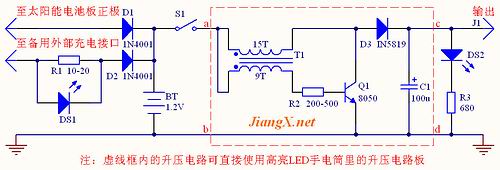
The circuit of the solar power supply board is shown in Figure 1. The solar charging circuit of the system is composed of D1 and BT. Usually, as long as a certain light intensity is reached, the solar panel charges the rechargeable battery BT through the diode D1 until it is saturated. In addition to the solar charging method, I also designed a spare external DC power charging interface to prevent accidents. The external charging circuit is composed of R1, DS1, D2 and BT. R1 selects the resistor with power of 1W. When R1 is 10 ohms, the optimal external charging voltage is 3-4 volts. DS1 is the external charging indicator. It is utilized. The voltage drop across resistor R1 illuminates. The latter boost circuit is boosted by the fast turn-off (off) characteristic of the intermittent oscillator. S1 is the power supply switch. When S1 is closed, the booster circuit starts to work, the solar power supply board can drive the load, J1 is the output interface, and DS2 is the output indicator.
Component selection
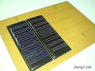
The price of commercially available solar panels is generally higher, but we don't have to buy a lot of solar panels, so it's moderate. According to the actual measurement, the single open circuit voltage of the solar panel used by the author in this production can reach 4.2V, and the short-circuit current can reach 38mA. The whole system is built on a universal circuit board (commonly known as "hole board"), so a universal board needs to be prepared. Figure 2 shows two solar panels and a hole plate prepared. The battery is equipped with a common No. 5 nickel-metal hydride rechargeable battery with a rated voltage of 1.2V. The boost circuit can use a ready-made boost circuit board inside a single cell highlight LED flashlight. The author is to remove a boosted circuit board inside a discarded single-cell highlight LED flashlight. If you need to do it yourself, the inductor T1 is wound 15 times and 9 turns on the small magnetic ring of Φ8mm with the Φ0.4mm enameled wire. The small magnetic ring can be removed from the waste energy-saving lamp. If the diode IN5819 can not be used, the IN4148 can be used instead. C1 uses a 100uF tantalum capacitor. If it is not, it can be replaced by an equivalent electrolytic capacitor, but the efficiency is slightly lower.

Production process
First, a small piece of wire is welded to the two electrodes of the solar panel as pins (Fig. 3) for easy connection and fixing on the board. Two solar panels are used for the positive pole to the positive pole, and the negative pole is used in parallel with the negative pole (marked above), which can effectively enhance the ability of the solar panel to supply current. After installing the solar panel, it is shown in Figure 4.
Install the rechargeable battery for energy storage. You can also connect the positive and negative terminals of the battery to the circuit board in the way shown in Figure 3. That is, the pins on the battery are soldered to the circuit board. For stability, you can use a pointed metal. The tool is drilled on the board and then reinforced with a nylon strap (Figure 5).

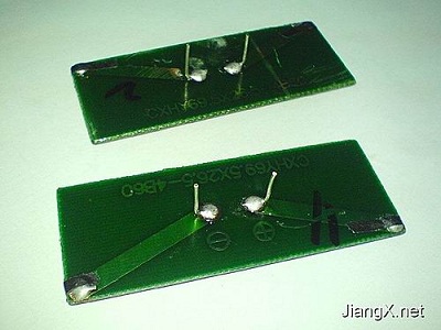
Next, connect the small booster board that was removed from the used single-cell highlight LED flashlight to the board. The two positive poles of the boosted circuit board connected to the battery are connected to point a in Figure 1, and the negative pole is connected to point b; the two wires connecting the LED lamps are connected to c point, and the negative electrode is connected to point d. When I made it, the boost board was connected to the underlying main board via DuPont pin headers (Figure 6). You can take your own method, as long as it is easy to make. If you are doing the boost circuit yourself, you can directly trace the line on the hole board. The component selection has been described in detail above and will not be repeated. The circuit is not complicated, you can play freely on the hole board.
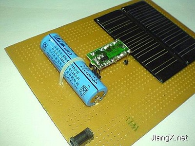
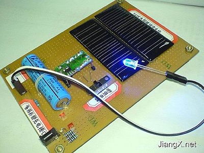
Figure 7 shows the finished solar power supply board. After it is made, it can supply some small things, such as flashlights and radios. After connecting a few white highlight LEDs, it becomes a solar LED flashlight. Figure 8 shows the scene where the solar power supply board lights up the bright LED.

Due to the lack of volume and lack of experience in the production, the board is chosen to be a bit large and has no outer casing. It is not easy to carry, so I hope that the fans will use their imagination to make the shape exquisite and compact. It is more convenient to carry while being aesthetically pleasing, increasing practicality.
1.Shape:Conoid ,Multi-pyramidal,Columniform,polygonal or conical
2.Material:steel plate.stainless steel compound plate,stainless steel plate,ect.(anticorrosion treatment with hot galvanization,also color polyester power could be coated on the surface)
High strength low alloy steel Q235,Q345,GR65,GR50 to ensure the mechanical properity of microelement in order to ensure the quality of galvanization (other materials are also avaliable on request)
3.Jointing of pole with insert mode,innerflange mode,face to face joint mode
4.Design of pole :against earthquake of 8 grade ,aganist wind pressure of 160
5.Minimum yield strength:355 mpa
6.Minimum ultimate tensile strength :490 mpa
7.Max ultimate tensilestrength:620 mpa
8.Certificate:ISO9001-2000
9.Length:Within 14m once forming without slip joint
10.Welding:It has past flaw testing.Internal and external double welding makes the welding beautiful in shape
11:Packages:Our poles as normal cover by Mat or straw bale at the top and bottom ,anyway also can following by client required , each 40HC or OT can loading how many pcs will calculation base on the client actually specification and data
Our lighting equipment are made from quality sheet from bending,forming,automatic welding and hot galvanization.We can reach one-run machining length of 14m,and can bend sheet thickness up to 25mm.We adopt advanced welding procedures ,automatically weld main joints and reach rank-II welding quality.
Octagonal Pole, Octagonal Street Light Pole, Octagonal Steel Pole, Octagonal Steel Electric Pole
YIXING FUTAO METAL COMPONENT UNIT CO.,LTD , http://www.chinasteelpole.com