
Since the development of automotive technology, electronic control units (ECUs) have been applied to all aspects of the interior of the car, and the technology is becoming more mature. As an important part of the body electronics, the development of the door electronic automatic control technology is also very rapid. However, in practical applications, all power windows or door devices have the potential to be stuck, which can cause injury. Therefore, in the door control system, the window anti-pinch design occupies an extremely important position.
This article refers to the address: http://
Most of the existing electric door control products with anti-pinch function have a commonality, that is, the MCU is the core in the hardware design, supplemented by power devices, control circuits and related communication modules (CAN or LIN). Cooperate with a series of control functions such as driving motor, lifting window, fault identification and diagnosis. However, such designs often encounter some technical bottlenecks, such as in the schematic design, the construction of MCU peripheral circuits, the selection of power devices, the matching and wiring between electronic components; in the PCB design, many devices must be considered. The layout and placement, the cumbersome and complicated routing, and the resulting poor EMC. Although these will not have a great impact on the overall function of the system, but the circuit reliability is not high, and in serious cases, the failure is frequent; in addition, a large number of electronic devices also invisibly increase the weight and cost of the product.
In response to this problem, we proposed another solution for the design of electric windows - with the TLE7810 chip from Infineon as the core, the peripheral is complemented by simple function modules, optimized design and also explored the TLE7810 power chip. The role in motor control.
Overall design and method solving
1 TLE7810 chip characteristics and advantages Because this door control system is designed for non-driver side electric windows, the production cost is as low as possible compared with the driver side electric windows; moreover, the non-driver side gating system does not require the rear view mirror The direction adjustment, the wiper and the external light control are greatly simplified. Therefore, the TLE7810 can be used to meet all requirements.
The TLE7810 is a highly integrated, low-cost smart power chip that integrates an 8051-compatible 8-bit microcontroller and an SBC (System-Basis-Chip) that supports on-chip debugging. 8-bit MCU has 16K flash, I/O port, Hall sensor interface, 10-bit A/D converter, power supply output and switch with sensor, integrated LIN bus transceiver, low voltage corrector LDO, two low Side switch (Relay drive) for on-chip debugging with overcurrent protection, watchdog, voltage monitoring, temperature monitoring and MCU monitoring and protection. The TLE7810 has two low-voltage wake-up modes: LIN bus wake-up and Wake-up pin wake-up.
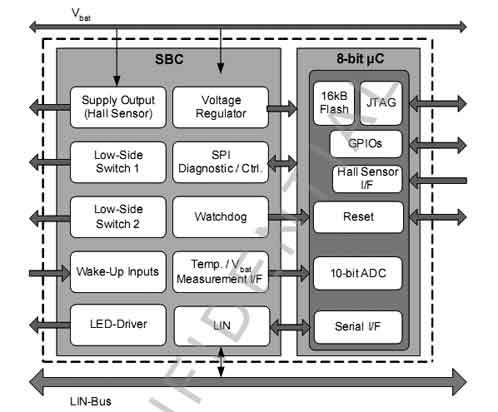
Figure 1 TLE7810 internal structure
Figure 1 is its structural module. It can be seen that the electronic control of the non-driver side window, the TLE7810 can not only meet the various indicators and requirements. Moreover, the "one core and two core" features simplify schematic design and PCB routing while reducing costs.
2 The window motor drive control design is based on the characteristics of the TLE7810. The overall block diagram of the design is shown in Figure 2.

Figure 2 hardware structure block diagram
The 12V VBAT voltage is connected to the TLE7810 and the execution motor for power supply. The 8-bit MCU in the TLE7810 communicates with the main controller (driver side) via the LIN bus. Its two low-side switches are connected to the Relay to control the switch on and off. Break, and then drive the H-bridge to control the motor. The Hall sensor TLE4966 collects motor operation information as feedback and sends it back to the MCU. The feedback includes two parts of the motor position and the direction of rotation, so as to record the working condition of the motor more accurately, and then control and identify the window lift and the stall of the motor to improve the working performance. In addition, PWM voltage regulation is also included in the design as an optional configuration.
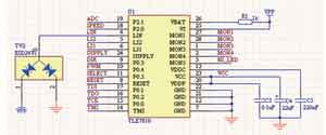
Figure 3 TLE7810 pin connection

Figure 4 TLE4966 Hall sensor peripheral circuit and connection
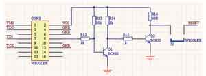
Figure 5 ULINK off pin input
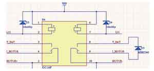
Figure 6 Relay Control
Figure 3 shows the pin connections for the TLE7810.
The input to the TLE7810 can be roughly divided into three parts. The first part is the button sampling input of MON1-MON4. The button is installed inside the door. When the passengers operate it, the control signal sent to the MCU through these four ports wakes up the MCU. The second part is the SPEED, DIR and SUPPLY Hall signal inputs corresponding to P2.0, P0.3 and SUPPLY. This part of the function is to receive the motor working status information from the Hall sensor TLE4966 (see Figure 4). Through these pins, the MCU can identify the working condition of the motor in time, and issue control commands to drive or stop the motor to respond to various sudden situations of motor operation. Therefore, this part of the input is very important. The third part is the ULINK related pin input, which is connected to JTAG (see Figure 5) for program download.
The output pin of the TLE7810 mainly outputs the switching signal, and controls the Relay (see Figure 6) to drive the motor. This part of the pin is mainly used to drive the high-side LED MON5 high-side switch, and the two low-side switches LS1 and LS2 are connected to the relay to drive the H-bridge to control the motor steering.
There are also some pins, such as LIN for communication with the host computer, PWM for starting the motor, RESET, VBAT, VS, etc. to form the smallest system of the TLE7810.
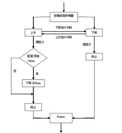
Figure 7 Anti-trap program flow diagram
The motor control program flow is shown in Figure 7. When the button signal is sampled or the control command sent by the host computer through LIN, the MCU is woken up and transferred to the motor control program. There are two modes of motor control window operation - up or down. During each mode execution, if the execution reverse direction run signal issued by the button is acquired, the program controls the motor to immediately switch to another operation mode. In the ascending mode, there are two cases in which the motor is blocked, that is, the glass is raised and the anti-clamping force is encountered during the ascending process. The difference between the two cases is mainly determined by whether the distance d from the upper edge of the motor-driven window to the window top is located. 4mm. When d≥4mm, the program calls the anti-pinch function, otherwise the motor stops. In the descent mode, the resistance mainly comes from the blocking force of the window running to the bottom, so the motor can be stopped directly.
Window anti-pinch verification and results According to the current practice, this project experiments equipped the motor with a double Hall sensor to sense whether the motor is subjected to resistance. In order to improve the experimental conditions and improve the accuracy of the experiment, a force sensor was used in the experiment to set and measure the anti-pinch force. Its advantage is to ensure that the clamping force at each position is less than 100N at different voltages (in the standard of the car factory) by comparison with the anti-pinch standard.
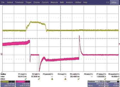
Figure 8 Force and current curves measured by the window anti-pinch experiment
The experimental steps can be generally divided into three steps: one, pressing the button to lift the motor to drive the window glass; second, applying a reverse force to simulate the anti-pinch force during the rising of the window glass; The situation, that is, the motor operation, records the relevant waveform.
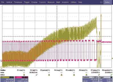
Figure 9 Current and Hall Relationship Waveforms
The anti-clamping force and motor current waveform recorded during the whole process are shown in Fig. 8. The yellow line is the force of the window glass, and the red line is the motor current curve. During the ascent of the window glass, the motor current is positive and is defined as forward rotation (the current zero offset is 9.9A), which is the rising direction of the window glass. The anti-clamping force is applied during the motor lift window, and the yellow line quickly climbs up to 100mV. What needs to be explained here is that according to the proportional relationship given by the sensor:
Anti-clamping force (N): voltage (mV) = 0.3
In this experiment, the 100mV of the yellow line should correspond to the anti-clamping force of 30N. The ECU successfully recognizes this obstacle and reacts. The motor is stopped by the program for 200ms. During this period, the current is zero, and the anti-pinch force still acts on the window. glass. After 200ms, the program controls the motor to rotate in the opposite direction to drive the window glass to move downwards. The current is negative. After the 200mm drop, the motor stops rotating and the current is zero. The whole experiment process ends. Fig. 9 is a diagram showing the relationship between the instantaneous current and the Hall sensor signal which are suddenly applied to the window glass. It can be clearly seen from the waveform in the figure that during the current climb, the signal period of the Hall acquisition increases due to the decrease of the motor speed. After the motor stops, the current drops sharply and the Hall period becomes infinite.
The conclusion can be concluded through a series of tests. Under normal circumstances, the TLE7810's anti-clamping force can basically be 20N, so that 80N rich (100~20N) can be used to deal with the deformation caused by window deformation or other unpredictable obstacles. . The anti-pinch force can be preset and adjusted to adapt to the window resistance that changes with environmental factors to stabilize the anti-pinch function, automatically correct the window end to ensure accurate window switching, motor overload current protection, progressive motor start and Stop operation, low power consumption mode, manual and automatic window control mode, integrated design for easy installation and cost reduction, complete power failure and fault protection.
Gun safe
Gun safes are secure and protective storage containers for one or more firearms, and/or ammunition for the respective firearms.
Details:
Safes are entirely made of steel;
Made by superior fire-proof materials and special sealing materials;
Shelves are removable and adjustable;
Door bolts are in a 4 way coverage;
All gun safes passed CE certification.
Gun Safety,Fire Proof Gun Safe,Furniture Fireproof Safe ,Fireproof Rifle Safe
YONGFA INTELLIGENT TECHNOLOGY SECURITY CO., LTD. , http://www.yongfa-safe.com