
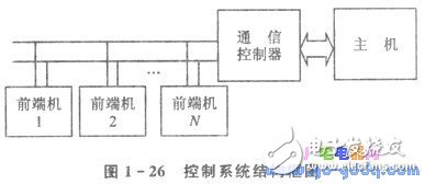
The front-end unit is built around an 8031 microcontroller system equipped with an RS-422 interface, located close to the control area. The communication controller acts as an interface card that houses an 8031 microcontroller in the IBM-PC/XT expansion slot, enabling intelligent communication between the host and the front-end device. Users only need to send simple commands from the host to the controller without needing to understand the underlying communication details, allowing the front-end to perform the required actions. Each data exchange between the controller and the host involves variable-length messages, but the size never exceeds 255 bytes. Error detection and correction mechanisms are implemented for every communication to ensure reliable data transfer. The IBM-PC/XT serves as the command initiator and the main controller of the entire system.
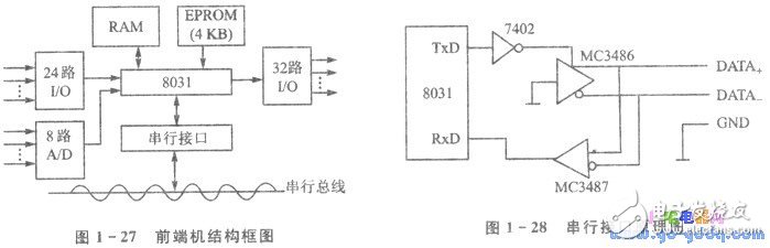
1. Front-End Machine
Figure 1-27 presents a block diagram of the front-end machine, which is based on a 51-series microcontroller system with an RS-422 serial interface. The number of input/output channels and analog-to-digital conversion capabilities is configured according to the specific needs of the application control system, such as an automatic vehicle testing line, and operates independently of the communication process. Figure 1-28 shows the schematic of the serial interface. Each front-end machine and the communication controller use differential drivers and receivers provided by MC3486 and MC3487. The serial bus consists of a twisted pair of DATA+ and DATA- lines. A termination resistor at the end of the twisted pair ensures the line is in a logic '1' state when idle. When a logic '0' (TxD=0) is transmitted, the line goes to a logic '0' state. This differential signaling meets the electrical standards of RS-422, offering better noise immunity, higher data rates, and longer transmission distances compared to RS-232.
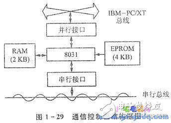
2. Communication Controller
Figure 1-29 illustrates the block diagram of the communication controller. The 8031 microcontroller communicates with both the front-end units and the host through its serial and parallel interfaces. The parallel interface schematic is shown in Figure 1-30. Data exchange between the controller and the IBM-PC/XT is handled via polling. The 8255A chip operates in Port A mode 2, which allows bidirectional data transfer. When the controller sends data to the IBM-PC/XT, the WR signal becomes active, writing data to Port A, which sets OBFA (Port A Output Buffer Full) to 1. The IBM-PC/XT then checks the status of 8212III and detects that OBFA is 0, allowing it to read the data from Port A. At the same time, the INT signal from 8212I resets OBFA to 0. When the IBM-PC/XT sends data to the controller, it writes the data to 8212II using an output command. Simultaneously, the INT signal from 8212II triggers a strobe signal on PC4 (STBA), setting PC5 (IBFA) to 1. The 8031 checks the C port of the 8255A and detects that IBFA is 1, then reads the data from Port A. The parallel port address is partially decoded, with 8212I and 8212II located at 02EOH, and 8212III at 02EIH.
Graded Radiator,Transformer Graded Radiators,Transformer Cooling Graded Radiator,Weather Proof Graded Radiator
Shenyang Tiantong Electricity Co., Ltd. , https://www.ttradiator.com