
When a PLC system operates over a long period, various faults may occur. Internal issues can often be identified through the PLC’s self-diagnostic functions, while external problems require analysis based on the program. Common faults include power supply failures, host unit malfunctions, communication errors, module defects, and software glitches.
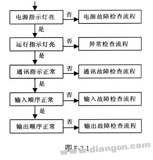
1. General Fault Inspection and Troubleshooting The main goal of the overall inspection is to identify the general location of the fault and then narrow it down step by step to pinpoint the exact cause. This systematic approach helps in efficiently resolving the issue. The general steps are illustrated in Figure F-2-1.
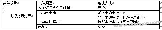
2. Power Failure Diagnosis and Resolution If any part of the power supply—such as the main unit, expansion unit, or module—shows abnormal behavior, a power failure check must be performed. If internal components are functioning correctly but only the LED display is faulty, no further action is needed. However, if the problem persists, the external power source should be checked first. If that is normal, then the internal power system should be examined. Detailed procedures are listed in Table F-2-1.
| Table F-2-1 |
|---|
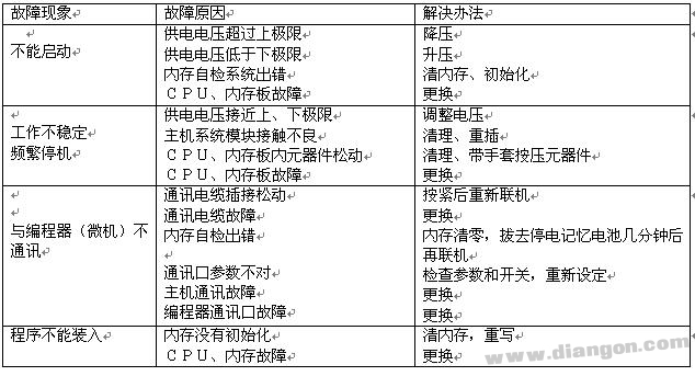
3. Abnormal Fault Diagnosis and Handling One of the most common issues is when the PLC stops running, even though the power indicator is on. In such cases, an abnormal fault check is necessary. The process is outlined in Table F-2-2.
| Table F-2-2 |
|---|
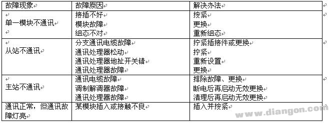
4. Communication Fault Diagnosis and Repair Communication is essential for the operation of a PLC network. If the main station, slave stations, or communication modules are not working properly, a communication fault check is required. The detailed procedure is shown in Table F-2-3.
| Table F-2-3 |
|---|
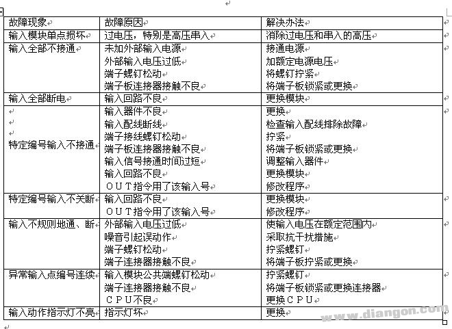
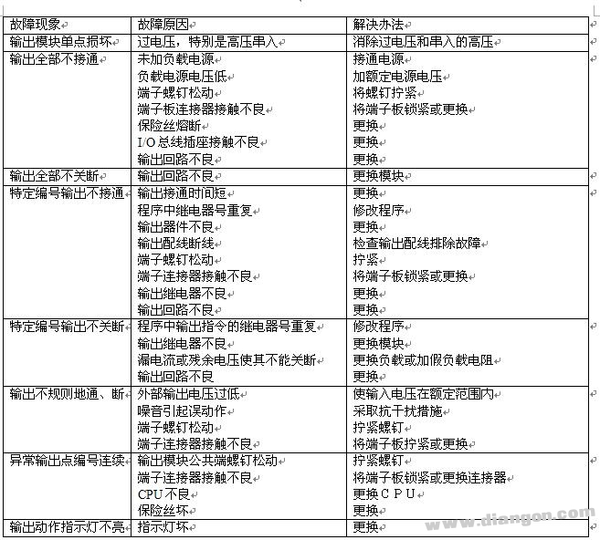
5. Input and Output Fault Diagnosis and Fixing The input/output modules are directly connected to external devices and are more prone to failure. Although these modules are easy to test and replace, it's crucial to determine the root cause, which is often related to external factors. Ignoring the cause can lead to repeated failures. The inspection steps are detailed in Tables F-2-4 and F-2-5.
| Table F-2-4 |
|---|
| Table F-2-5 |
|---|
4. Installation Status: Ensure all units are securely fastened. Check if the cable connectors are properly fixed and if the terminal screws are tight. No looseness or abnormalities should be present.
5. Life Components: Battery, relay, memory, and other components should be checked against their respective specifications.
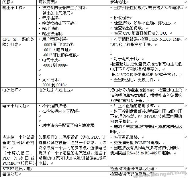
F.4 Programmable Controller Troubleshooting Guide While specific PLC troubleshooting may vary, the following methods apply to the S7-200 series. Refer to Table F-4-1 for details.
| Table F-4-1 |
|---|
It should be noted that PLCs are highly reliable and stable systems. As long as they are installed and operated according to technical guidelines, the chance of failure is extremely low. However, in case of malfunction, it's important to follow the diagnostic steps above. Always check for damage caused by external equipment and ensure the root cause is identified before attempting to restart the system.
Wuxi Motian Signage Co., Ltd , https://www.makesignage.com