
The basic structure of a motor includes a stator winding, which generates a magnetic field, and a rotor, which rotates under the influence of this field. The rotor typically consists of a squirrel-cage aluminum frame that carries current when exposed to the rotating magnetic field produced by the stator. This interaction causes the rotor to rotate, producing mechanical motion.
Stator (Stationary Part)
The stator core forms part of the magnetic circuit and houses the stator windings. These windings are connected to three-phase alternating current, creating a rotating magnetic field. The base of the motor supports the stator core and end caps, ensuring stability and providing protection and heat dissipation for internal components.
Rotor (Rotating Part)
The rotor core contains slots where the rotor windings are placed. These windings interact with the rotating magnetic field from the stator, inducing electromotive force and current, which in turn produce electromagnetic torque to drive the motor.
1. DC Motor A DC motor is a type of electric motor that converts direct current (DC) electrical energy into mechanical energy. When used as a generator, it performs the reverse process, converting mechanical energy into electrical energy. DC motors are widely used in applications requiring precise speed control and high starting torque.
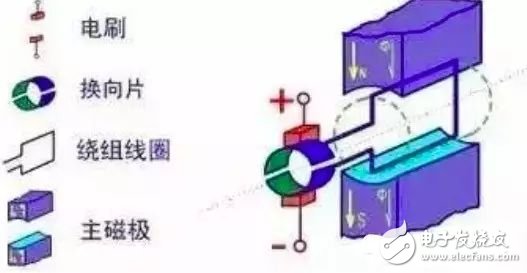
â–² Physical model diagram of DC motor The diagram shows a fixed magnet (main pole) and brushes on the stationary part, while the rotating section has a toroidal core with windings wrapped around it. This setup allows the motor to convert electrical energy into mechanical rotation.
2. Stepper Motor A stepper motor is an open-loop control element that converts electrical pulse signals into angular or linear displacement. It is widely used in precision positioning systems. The motor's speed and position depend solely on the frequency and number of input pulses, making it highly accurate and reliable.
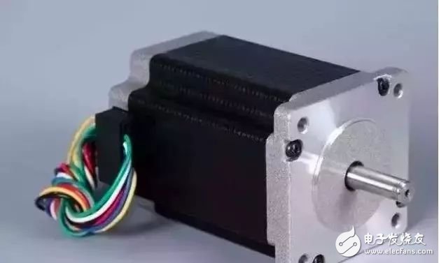
Stepper motors operate by energizing the stator windings in a specific sequence, which creates a rotating magnetic field. The rotor aligns with this field, moving in discrete steps. Each pulse advances the rotor by a fixed angle, allowing for precise control over movement and speed.
Stepper Motor Working Principle When current flows through the stator windings, a vector magnetic field is created. This field induces currents in the rotor, generating torque that causes it to rotate. By changing the sequence of energization, the direction of rotation can be reversed. The number of pulses controls the position, while the frequency determines the speed.
3. Single-Phase Induction Motor An induction motor, also known as an asynchronous motor, operates based on the interaction between the rotating magnetic field in the stator and the induced current in the rotor. It is commonly used in household and industrial applications due to its simplicity and reliability.
Single-Phase Induction Motor Principle In a single-phase AC motor, the stator winding produces a pulsating magnetic field when connected to an AC supply. This field can be decomposed into two rotating fields in opposite directions. These fields induce currents in the rotor, generating both forward and backward torques. The net result is a rotational motion that drives the motor.
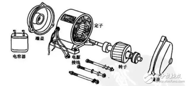
Disassembled Single-Phase Induction Motor This image shows the internal components of a single-phase induction motor, including the stator and rotor. Understanding these parts helps in grasping how the motor functions in real-world applications.
4. Permanent Magnet Motor A permanent magnet motor uses permanent magnets instead of electromagnets to create the magnetic field. This design offers higher efficiency and better performance in certain applications. The motor requires both a magnetic field and a current-carrying conductor to produce motion.
Permanent magnet motors are widely used in electric vehicles, robotics, and other high-performance systems. Their ability to maintain a strong magnetic field without external power makes them ideal for energy-efficient designs.
Motor Sectional View Shows How It Works This view illustrates the internal structure of a permanent magnet motor, highlighting the role of the stator and rotor in generating motion.
Graphic | High Efficiency Motor and System Energy Saving Efficient motors play a crucial role in reducing energy consumption and improving system performance. Modern designs focus on minimizing losses and maximizing output, contributing to sustainable technology development.
Waterproof Dustproof Scanner,Dustproof Scanner,Waterproof Scanner,Waterproof Dustproof Scanners
Guangzhou Winson Information Technology Co., Ltd. , https://www.barcodescanner-2d.com