
Usually after Auto Setup, the waveform will appear on the screen, and then the measurement analysis can be performed, but Auto Setup does not guarantee that the signal is captured by high fidelity. The high fidelity capture signal is the first element, otherwise the subsequent measurement analysis It doesn't make sense, so how can we better observe the waveform? You will know after reading this article.

How to better observe the waveform is essentially to focus on the measurement and analysis of the points of interest. How to capture the waveform with high fidelity begins with the process of processing the signal from the oscilloscope.
After the signal is processed by the oscilloscope front-end circuit, it comes to the ADC for analog-to-digital conversion. Then the signal is reconstructed and restored. Here is the focus of this article, the oscilloscope capture mode. There are generally four ways to capture, different ways of capturing, suitable for observing different signals. Next, let's take a brief introduction to how the oscilloscope handles the sampling points, that is, the oscilloscope's capture mode.
Standard capture modeThe first is the standard capture mode, in which the oscilloscope samples the acquired signals at equal intervals.
The standard capture mode of operation also guarantees the most primitive state of the signal. For most waveforms, this mode produces the best display. The following is the default capture mode of the ZDS2000 Series oscilloscope.

Figure 1 Standard capture mode
Peak capture modeThe next step is the peak capture mode. When you look at the name, you know what it means to acquire the maximum and minimum values ​​in a sample interval signal.
In this mode, the occasional narrow pulse width can be effectively observed. It is very useful in capturing high frequency glitch. It can acquire the envelope of the signal or the narrow pulse that may be lost. Using the peak capture mode will compare the noise of the waveform display. obvious.
Average capture modeThe third is the average capture mode. The name is also very easy to understand. It is to capture the N-screen signals, put them at the trigger position, and then do the averaging.
Using the average acquisition mode, while reducing the noise while maintaining the original bandwidth, filtering out the noise is beneficial for measuring the signal. It is suitable for observing periodic repetitive signals, and its filtering effect improves the vertical resolution of the oscilloscope. It is worth mentioning that the average capture is particularly suitable for performing harmonic analysis or power quality analysis.

Figure 3 average capture method
High resolution capture modeThe last is the high-resolution capture mode. For example, the working principle is to divide a waveform into 5 parts, then average each point of a waveform, and finally the waveform becomes 5 points. This kind of processing can effectively improve the equivalent resolution of the system, and is essentially a digital filtering. The more the number of sampling points used for averaging, the more the resolution is increased, and the displayed waveform is smoother, thereby achieving the purpose of reducing noise.
It should be noted that the high resolution is to average the adjacent points of a waveform, so the mode is to improve the test accuracy by sacrificing the bandwidth of the non-repetitive signal, so it is not suitable for testing high frequency signals, and is suitable for observation. High resolution and lower bandwidth waveforms.
Four capture modes measured and comparedAfter understanding the working principle of the four capture modes, let's make a comparison. When inputting the same signal, the noise in the signal can be observed in the standard capture mode. The noise of the signal in the peak capture mode is more obvious. In the average capture mode and the high-resolution capture mode, almost no random noise is seen.
According to the type of signal to be tested and the test points that need to be concerned, setting the corresponding capture mode can help us better observe the waveform and find and solve the problem faster.
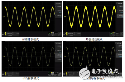
Figure 5 Comparison of four capture modes
eSky 4G GPS Trackers supports Cat-1, Cat-4, Cat-M and NB-IoT. Tracking, geofence, backup battery, Over speed limit, 3-Axis Accelerometer, Storing Message, Low Voltage Detection, Power Saving Mode, Expand Other Peripherals, and OTA (Over the Air) are all the basic features. We also have trackers with upscale features like fuel, temperature monitoring and with RS232, RS485. These are Robust and affordable vehicle tracking device with inputs/outputs, remote immobilization for fleet management, driver ID, driver safety and behavior monitoring, theft recovery, and more.
All Kinds of 4G Cat-M Vehicle GPS Tracker, there must be one which should meet your expectation.
CAT-M vehicle GPS Trackers,CAT-M car GPS Trackers,Waterproof vehicle GPS Tracker, IP65 vehicle GPS Tracker,OBDII CAT-M vehicle GPS Trackers,Wireless CAT-M GPS Trackers
eSky wireless Inc , https://www.eskygpsiot.com