
The AC voltage regulator regulates the AC voltage and adjusts the voltage within the specified voltage input range to stabilize the output voltage within the specified range of electrical equipment.
AC voltage regulator worksThere are many types of AC voltage regulators, and the main circuit works differently, but basically (except AC parameter regulators) are basically input switch sampling circuits, control circuits, voltage regulating devices, output protection devices, driving devices, displays. And composition, the basic working principle block diagram is as follows:
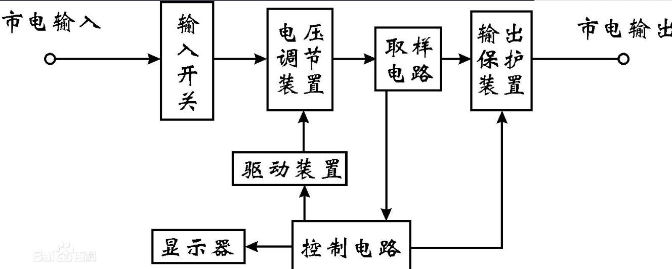
1. Input switch: As the input switch of the voltage regulator, the air switch type small open circuit switch with limited current protection is generally used, which can protect the voltage regulator and the electric equipment.
2. Voltage regulating device: It is a device that can adjust the output voltage. It can raise or lower the output voltage as the most important component of the regulator.
3. Sampling circuit: It detects the output voltage and current of the regulator and transmits the change of the output voltage to the control circuit.
4. Drive device: Since the control circuit of the control circuit is weak, it is necessary to use the drive device for power amplification and conversion.
5, drive protection device: a device to connect and disconnect the output of the regulator, generally used relays or contactors or fuses.
6. Control circuit: It analyzes the sampled circuit detection type. When the output voltage is high, the control signal is sent to the driving device to lower the voltage. The driving device will drive the voltage regulating device to lower the output voltage when the output is output. When the voltage is low, a control signal for raising the voltage is sent to the driving device, and the driving device adjusts the output voltage by the driving voltage adjusting device to stabilize the output voltage to achieve stable output.
When it is detected that the output voltage or current is outside the control range of the regulator. The control circuit will control the output protection device to turn off the output to protect the electrical equipment, while the output protection device is connected to the output when normal, and the powered device can obtain a stable voltage supply.
Classification of AC voltage regulators
AC stabilized power supplies are widely used and have many types, which can be roughly divided into the following six types.
1 Ferromagnetic resonant AC voltage regulator: AC voltage regulator made by constant voltage volt-ampere characteristics after combination of saturated choke coil and corresponding capacitor. Magnetic saturation is an early typical structure of this type of regulator. The utility model has the advantages of simple structure, convenient manufacture, wide input range of the input voltage, reliable operation and strong overload capability. However, the waveform distortion is large and the stability is not high. The stabilized voltage transformer is also a power supply device that achieves voltage regulation by means of nonlinearity of electromagnetic components. It differs from a magnetically saturated regulator in the form of the magnetic circuit structure, and the basic working principle is the same. It achieves both voltage regulation and voltage conversion on a single core, so it is superior to ordinary power transformers and magnetic saturation regulators.
2 magnetic amplifier type AC voltage regulator: A device that connects a magnetic amplifier and an autotransformer in series, and uses an electronic circuit to change the impedance of the magnetic amplifier to stabilize the output voltage. The circuit form can be linear amplification or pulse width modulation. This type of regulator has a closed loop system with feedback control, so the stability is high and the output waveform is good. However, due to the use of a magnetic amplifier with a large inertia, the recovery time is longer. Because of the auto-coupling method, the anti-interference ability is poor.
3 Sliding AC Regulator: A device that changes the position of the sliding contact of the transformer to stabilize the output voltage, that is, an automatic voltage regulator AC regulator driven by a servo motor. This type of regulator has high efficiency, good output voltage waveform, and no special requirements on the nature of the load. However, the stability is lower and the recovery time is longer.
4 Inductive AC Regulator: A device that stabilizes the output AC voltage by changing the phase difference between the secondary voltage of the transformer and the primary voltage. It is similar in structure to a wire wound asynchronous motor and is similar in principle to an inductive voltage regulator. It has a wide voltage regulation range, good output voltage waveform, and power can be hundreds of kilowatts. However, since the rotor is often in a locked state, the power consumption is large and the efficiency is low. In addition, due to the large amount of copper and iron materials, it is less produced.
5 Thyristor AC Regulator: An AC regulator that uses a thyristor as a power conditioning component. It has the advantages of high stability, fast response and no noise. However, due to damage to the mains waveform, it causes interference to communication equipment and electronic equipment. 6 relay type AC voltage regulator: Use the relay as the AC voltage regulator to adjust the winding of the autotransformer. It has the advantages of wide voltage regulation range, fast response speed and low production cost. Used in street lighting and more remote home use.
With the development of power technology, the following three new types of AC regulated power supplies have appeared in the 1980s. 1 compensating AC voltage regulator: also known as partial adjustment regulator. The additional voltage of the compensation transformer is connected between the power supply and the load. With the input voltage, the intermittent voltage switch (contactor or thyristor) or the continuous servo motor is used to change the magnitude or pole of the additional voltage. Sexuality, subtract (or add) the input voltage from the upper part (or the insufficient part) to achieve the purpose of voltage regulation. The compensation transformer capacity is only about 1/7 of the output power, and has the advantages of simple structure and low cost, but the stability is not high. 2 digital-controlled AC voltage regulator and step-type voltage regulator: The logic circuit or the microprocessor forms the control circuit, and converts the primary turns of the transformer according to the input voltage level to stabilize the output voltage. 3 Purifying AC Regulator: Due to its good isolation, it can eliminate the spike interference from the power grid and get applied.
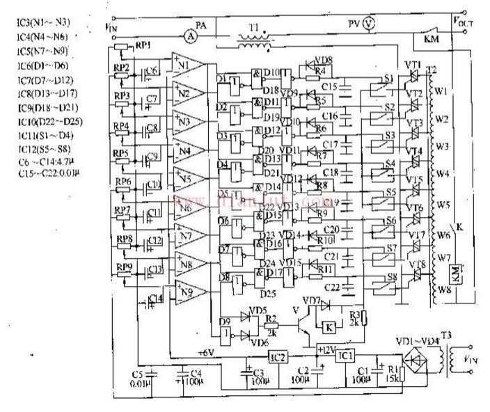
AC voltage regulator circuit diagram (1)This example introduces a compensated non-contact AC automatic voltage regulator, which uses the primary voltage of the control transformer to change the secondary compensation voltage, and solves the phenomenon of instantaneous power-off of the line voltage regulation. The input voltage of the AC voltage regulator is AC 167-264V, and the output voltage is AC 220 (1 5%) V.
Circuit working principle
The AC voltage regulator circuit is composed of a power voltage regulator circuit, an input comparison circuit, a code control circuit, a compensation output circuit, and an overvoltage/undervoltage protection circuit, as shown in Figure 5-40.
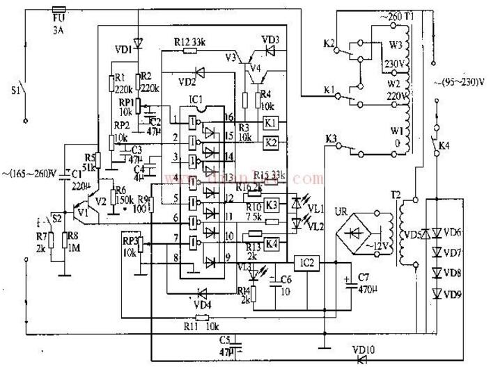
The AC voltage regulator introduced in this example has the functions of automatic voltage regulation and voltage regulation, no-load power-off energy-saving and over-voltage power-off protection. Its input voltage range is AC 165-260V, and the output voltage is AC 195-230V. The power is 500W.
Circuit working principle:
The AC voltage regulator circuit is composed of a power supply voltage stabilization circuit, a voltage detection, a control circuit and a delay circuit, as shown in Figure 5-41.
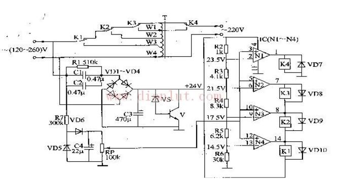
The AC voltage regulator introduced in this example has the function of automatic voltage regulation. Its input voltage range is AC-120-260V, the output voltage is AC 220 (1±10%)V, and the output power is 300-1000W. Depending on the power of the transformer and the contact current capacity of the relay).
Circuit working principle
The AC voltage regulator circuit is composed of a power supply circuit and a voltage detection control circuit, as shown in Figure 5-42.
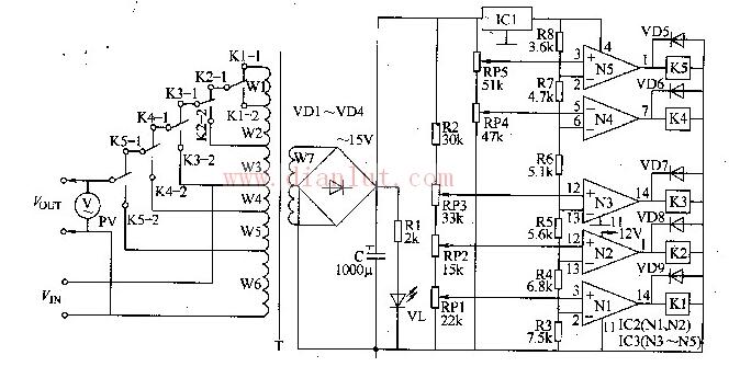
The AC voltage regulator introduced in this example has an input voltage range of 160-270V, an output voltage of 220 (1 ± 5%) V, and an output power of 600-800W, which can meet the requirements of general household appliances.
Circuit working principle
The AC voltage regulator circuit is composed of an up/down voltage switching circuit and an automatic control circuit, as shown in Figure 5-43. The rising/lowering voltage switching circuit consists of the Wl-W6 winding of the power transformer T and the normally closed contact Kl-l of the relay.
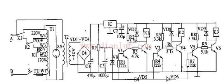
This example introduces a boost AC voltage regulator with an input voltage of 150-230V and an output voltage of 220 (1 5%) V, which can be used in homes where the supply voltage is unstable and the voltage is low.
Circuit working principle
The AC voltage regulator circuit is composed of a power supply circuit, a voltage detection circuit and a boost control circuit, as shown in Figure 5-44.
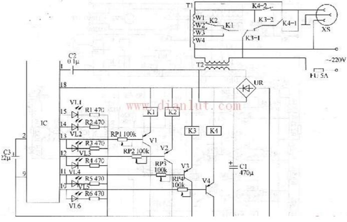
This example introduces an AC voltage regulator controlled by the SL322 LED driver IC. It can be used as both an automatic voltage regulator and a voltage light display. It can be used in areas where the market power is often low.
Circuit working principle
The AC voltage regulator circuit is composed of a power supply circuit, a voltage detection control circuit and a control execution circuit, as shown in Figure 5-45.
Heated Seat Cushion,Heated Seat Cushion for Office Chair,Heated Seat Cushion USB,Electric Heated Seat Cushion
Ningbo Sinco Industrial & Trading Co., Ltd. , https://www.newsinco.com