
0 Introduction <br> The mission of the intelligent wheelchair is to safely and conveniently deliver the user to the destination and complete the assigned task. In the process of exercise, the wheelchair needs to accept the user's instructions, and also needs to combine the environmental information to start its own function modules such as obstacle avoidance and navigation. Unlike the mobile robot, the wheelchair and the user become a cooperative system during use. This requires taking human factors into consideration at the beginning of design. Therefore, safety, comfort and ease of operation should be the most important factors in the design of intelligent wheelchairs. The difference in physical fitness of users determines that smart wheelchairs need to be designed as A multi-functional electronic system that meets multiple levels of needs, and modularity best reflects the characteristics of the system's multi-functionality. Each user can select the appropriate module integration according to their own type and degree of disability, and the designer can The wheelchair function is easily improved by adding functional modules on an existing basis. This article focuses on the modular design of smart wheelchairs.
1 Sensor system overall structure design <br> The total function of the intelligent wheelchair can be divided into the following sub-functions: environment awareness and navigation functions, control functions, drive functions and human-computer interaction functions. Through the functional analysis and module division of the intelligent wheelchair, combined with the specific research content and expected control objectives, the system is mainly composed of sensor module, drive control module and human-computer interaction module. The hardware system structure is shown in Figure 1. The sensor module mainly consists of two parts: internal state perception and external environment perception. The attitude sensor is used to determine the position information of the wheelchair itself. The self-positioning information is obtained by the displacement speed and distance of the encoder. The visual, ultrasonic and proximity switches are mainly responsible for continuous acquisition. Distance information of the surrounding environment and obstacles. Drive Control Module We use rear-wheel drive mode. Each rear wheel is equipped with an electric motor to realize the forward, reverse and steering of the electric wheelchair under the operation of the controller. The human-computer interaction interface is implemented by the joystick and personal computer interface data input to achieve basic human-computer interaction.

Among them, the data acquisition unit intends to select DSP TMS320LF2407A as the control chip of the sensor module. The TMS320LF2407A is a high performance digital signal processor with high frequency and rich peripheral interface. Its main frequency can reach 150MHz, low power consumption (core voltage 1.8V, I/O voltage 3.3V); 128kXl6 bit on-chip FLAsH, 18kXl6-bit on-chip SRAM, 4kXl6-bit on-chip ROM; peripherals for motor control, 2 Event manager; multiple standard serial peripherals, 1 SPI synchronous serial port, 2 UART asynchronous serial ports, 1 enhanced CAN bus interface, 1 McBSP synchronous serial port; 16 channel 12-bit A/D converter; 56 Independently programmable, multiplexed, general purpose I/O ports. Can meet the requirements of this system design.
2 Multi-sensor data acquisition and processing <br> The intelligent wheelchair of this system has 2 independent drive wheels, each equipped with a motor code wheel. The real-time detection data of the two motor code disks constitutes an odometer-type relative positioning sensor, and a tilt sensor and a gyroscope are installed to measure the posture state of the wheelchair during traveling. Ultrasonic sensors and proximity switches are used to sense ambient information. In order to obtain a wider range of obstacle information, the system is equipped with 8 infrared sensors and 8 ultrasonic sensors. In addition, a CCD camera is installed to determine the depth information in the forward travel path.
2.1 Ultrasonic Sensor and Proximity Switch This ultrasonic ranging system has 8 ultrasonic sensors, which form an array of ultrasonic sensors, which are placed in two around the wheelchair. In order to detect some obstacles that were missed or failed to be processed in time by the ultrasonic sensor, four inductive proximity switches were added around the wheelchair. When the obstacle hits the anti-collision rubber ring, the metal strip is deformed, and the displacement in the vertical direction is generated, and the proximity switch action is triggered to obtain a switch signal (interrupt request signal), so that the mobile robot stops immediately.

The ultrasonic environment detecting circuit is mainly composed of a multi-channel analog switch, a boosting amplifying circuit, a buffer amplifying shaping circuit and an ultrasonic transducer, as shown in FIG. 2 .
The boost amplifying circuit and the ultrasonic transmitting transducer constitute an ultrasonic transmitting portion. The transmitting process is: firstly, a modulated pulse wave of a certain pulse width is generated by the pulse width modulation channel of the DSP, and an instantaneous high-energy signal is generated by the transformer boosting amplifying circuit, and the ultrasonic transmitting transducer is excited to generate an ultrasonic signal. It should be noted that at the moment of the ultrasonic wave, some of the sound waves will directly enter the ultrasonic receiving end, thereby generating a strong false reflected wave, causing a so-called ringing phenomenon. In order to avoid ringing, software delay processing is required, resulting in detection of dead zones. In the program processing, the corresponding CAP interrupt is closed within a period of time after the DSP transmits the excitation pulse wave, and the CAP interrupt is opened after the blind zone interval has elapsed. The receiving part of the ultrasonic wave must work in coordination with the transmitting part to ensure that the signal is received accurately and sensitively. This part is mainly composed of ultrasonic receiving transducer, amplification filtering and shaping trigger output circuit. Since the energy of the ultrasonic wave is reduced as the propagation distance increases, the echo signal reflected back from the long distance obstacle is generally weak, so it needs to be multi-stage signal amplification processing before it can be interrupted by the DSP input. The port was detected.
2.2 Encoder In the intelligent wheelchair system, in addition to measuring the distance information of the environment, it is sometimes necessary to effectively observe or estimate the position information. For most indoor mobile robot systems, the orientation information is generally estimated indirectly through the code wheel information. This system also uses this method. The result is obtained by calculating the information read from the code wheel at the cost of a certain calculation time.
There are two time management modules (EVs) on the TMS324LF2407A chip. Each EV module has an orthogonal coded pulse circuit. After using this circuit, quadrature coded pulses can be input on two corresponding pins. This circuit can be used to connect the optical encoder to obtain information such as the position and velocity of the rotating machine, but it should be noted that the capture function on the corresponding pin must be disabled at this time.
The timing of the orthogonal coded pulse circuit can be provided by a general-purpose timer 2 (or a general-purpose timer 4, an EVB module), which must be set to an directional up/down mode, and a quadrature-coded pulse circuit as a clock source.
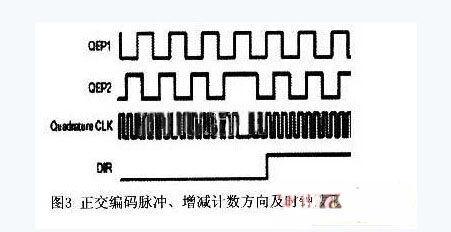
The orthogonal coded pulse is a pulse with two frequency variations and orthogonal (phase difference of 90°). It is generated by the photoelectric encoder on the motor shaft. The code wheel is on the motor shaft and has many empty wire slots. When the motor drives the code wheel to rotate, if the light emitted by the LED is blocked, the rear photoelectric sensor will not receive the signal, and then the photoelectric sensor emits a low-level pulse, that is, “0â€. If the rotation position is just right, the light source can be transparent. The light trough, when the photoelectric sensor senses the signal, it sends a high-level pulse, which is "1".
The direction detection logic of the orthogonal coded pulse circuit determines which of the two pulse sequences is the pilot sequence, and then it generates the direction signal as the count direction input of the general-purpose timer, and the two edges of the two columns of the orthogonal input pulse are positive. The interleaved pulse coding circuit counts, therefore, the generated clock frequency is four times that of each input sequence, and this clock is used as the input clock of the general-purpose timer 2 or 4. Figure 3 shows the waveforms of the orthogonally encoded pulses, the up-and-down counting direction, and the clock.
2.3 Attitude Sensor One of the most striking features of this system that distinguishes it from other wheelchair designs is that the design can rely on two wheels to complete the balance of the car body. This remarkable feature requires that it has a special structure. The basic design idea is to keep the two wheels driven by independent DC motors, and on one axis, the center of gravity of the car body is kept above the axle, using the angle of inclination of the car body. The sensor acquires the attitude information of the vehicle body in real time, and the processor of the robot processes the sensor signal, calculates the control quantity to control the rotation speed and steering of the motor according to a certain control algorithm, and drives the robot to advance or retreat to complete the balance of the vehicle body.
The intelligent wheelchair uses a combination of a tilt sensor and a gyroscope to form an attitude sensor to detect the running posture of the vehicle body platform. The tilt sensor is used to measure the angle of the wheelchair from the vertical direction, and the gyroscope is used to measure the angular velocity.
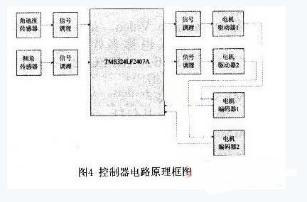
The motion controller with TMS320LF2407A as the control core, according to the displacement and attitude signals of the platform operation detected by the encoder and attitude sensor, calculates the control amount through a certain control strategy, and then drives the DC motor through the pulse width modulation control and the driver amplification. Operation, adjust the running speed of the car body platform at any time, so that the car body platform is always in balance. The schematic diagram of the control circuit is shown in Figure 4. The control board collects signals from the tilt and angular velocity sensors and conditions (filters, shapes, shifts) the signals, and then transmits the signals to the control board for processing by the DSP (the control algorithm is derived from the mathematical model of the electric vehicle system) Out), the control signal is sent through the two-way pulse width modulation of the DSP, and then the motor is driven by the motor drive module to control the balance of the wheelchair.
2.4 The camera is used to sense the depth information of the environment, such as determining whether there is a staircase in front and extracting the height information of the stairs, extracting the road markers for navigation, and the like. The camera can communicate directly with the PC via USB and is not described here.
3 Conclusion <br> This paper designed a multi-sensor environment-aware system for intelligent wheelchairs. The data acquisition subsystem was introduced in detail, and the environmental information was perceived by simple and reliable hardware circuits. The experiment proves that the system scheme has the characteristics of simple hardware circuit structure, reliable operation, high precision and good repeatability, and adopts modular design, which can more easily add newly developed functional modules and update technology to facilitate consumers. According to the needs of their own lives, each module is selected and combined so that each functional module can be fully applied to meet the needs of different consumer classes.
A blower motor is the component within a home`s HVAC system. The motor blows heated air through vents when the heating system is in use. Conversely, some Blower Motors blow cold air when the air conditioning system is in use.
There are two main types of blower motors: single-speed motors and variable-speed motors. Single-speed blower motors blow air at one speed. Variable-speed motors adjust their speed to blow air at varying speed levels.
A properly functioning blower motor remains a critical component of your home`s HVAC system. The blow motor is vital in maintaining a comfortable temperature within your home.
Blower Motors
blower motor,furnace blower motor,ac blower motor,hvac blower motor,heater blower motor,blower fan motor
Shenzhen Maintex Intelligent Control Co., Ltd. , https://www.maintexmotor.com