
This paper presents an online monitoring and management system for lithium iron phosphate battery packs based on LIN bus. The system uses a distributed network control structure. Through the design of the Dspic30f4012 chip as the core underlying hardware, it realizes accurate monitoring of lithium iron phosphate battery parameters, realizes data transmission through LIN bus technology, and is based on a more accurate battery model basis The extended Kalman algorithm is used to estimate the battery state of charge (SOC), which improves the estimation accuracy. The experimental results show that the system can perform real-time dynamic monitoring and effective protection of the battery pack, and provides application value for the development of an intelligent battery management system for electric vehicles.

As a new type of electric vehicle power battery, lithium iron phosphate battery has the advantages of large capacity, high safety, high temperature resistance, especially long cycle life. Its cycle life is at least 4 times higher than that of ordinary lead acid batteries. It has great application potential in the market. When there is no fundamental breakthrough in the capacity of power batteries at this stage, the application of battery management system (BMS) in electric vehicles will be extremely important. It can detect the voltage, current and temperature of power batteries in real time, and Use these parameters to estimate the state of charge (SOC) of the battery and provide the driver with a reference to the vehicle's driving range; in addition, BMS can alarm and protect the battery's overcharge and overdischarge, and the battery pack and single battery Carry out effective protection, so as to improve battery performance and battery life. LIN bus is a low-cost automotive Class A bus, which is very suitable for data transmission with low real-time requirements such as temperature and current. The bus-based transmission of data through LIN bus further reduces costs.
1 The overall structure and function of the system
In this design, the battery management system is divided into two parts: signal detection module, communication and information processing module. In the signal detection module, each cell corresponds to a bottom ECU (Dspic30f4012), which can realize cell voltage collection, current detection, and temperature sampling; at the same time, it can also detect the voltage, current and ambient temperature of the entire battery pack for the battery The detection and protection during general charging and balanced charging are shown in Figure 1.
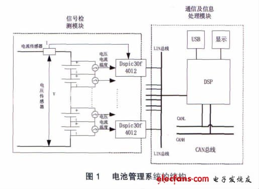
The bottom layer ECU encapsulates the detected voltage, current, temperature and other variables into a LIN bus frame format, and then communicates with the upper layer ECU through the LIN bus. The information processing module can realize the real-time estimation and fault analysis of the state of charge of the power battery, and display the temperature, voltage, current and other information.
2 battery management system design
2.1 Basic hardware design of battery management system
Due to the large number of cells in the battery pack, this system uses a distributed structure, which can effectively reduce the sampling line crossing the battery, reduce the complexity of installation and commissioning, and also reduce potential safety hazards. The bottom ECU uses the Dspic30f4012 chip, which can work in the temperature range of -40 ~ 125 ℃, which is an automotive-grade chip; it has a wealth of analog, digital I / O interfaces, 10-bit A / D conversion function, and SCI communication function, etc. .
2.1.1 Design of signal acquisition module
Dspic30f4012 has a wide operating voltage range of 2.5 ~ 5.5 V, so it can be directly powered by a single lithium iron phosphate battery. Only a 0.1 μF filter capacitor is needed to make the chip work, and the power supply circuit is greatly simplified. Because the internal reference voltage for A / D conversion is not provided in the F4012 chip, when performing voltage detection, an external A / D conversion reference voltage is required. In this paper, the LM385 with low power consumption and low voltage error is used to provide an external reference of 2.5 V Voltage, as shown in Figure 2.
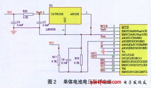
The characteristic of the voltage detection module in this design is that each detection module separately detects the voltage on each single battery, instead of realizing it through the traditional multi-way switch time-sharing selection method, which fully realizes a purely distributed battery management structure . The voltage of the lithium iron phosphate battery is directly drawn from the two ends of the single cell, and then divided by two high-precision resistors. The divided voltage is introduced into the A / D analog signal conversion channel inside the Dspic30f4012 chip for voltage detection. . The A / D converter in the Dspic30f4012 chip is 10-bit precision and the reference voltage is 2.5 V, so the voltage detection module can detect a voltage range of 0 ~ 5 V, which is greater than the maximum voltage of the single cell 3.65 V. The total voltage of the battery pack In the detection, the signal attenuation circuit and the anti-common mode voltage circuit are connected to the A / D conversion channel in the Dspic30f4012 chip to complete the collection of the battery pack voltage.
The detection of the current of the single battery is realized by the Hall sensor. The Hall sensor can output a voltage signal of up to 3 V, which can be directly connected to the A / D sampling channel in the Dspic30f4012 chip; the temperature of the battery is detected by the TJ1047 temperature detection To achieve this with a chip, the output voltage of the TJ1047 temperature detection chip at -40 ℃ and 125 ℃ is 0.5 V and 1.75 V, respectively, and has a temperature-voltage proportional characteristic of 10 mV / ℃ and an error of ± 0.5 ℃. Therefore, the voltage output from the TJ1047 chip can be directly connected to the A / D conversion channel in the Dspic30f4012 chip to complete the collection of battery temperature and ambient temperature.
2.1.2 LIN communication interface design
In modern vehicles, the bus technology is more and more applied, CAN / LIN network has become the mainstream development direction of distributed-based in-vehicle electronic networks. As a high-speed transmission bus, CAN bus has the outstanding characteristics of fast speed, high bandwidth, and many functions, but its cost is relatively expensive; LIN bus is a low-end bus, but it has outstanding advantages in reducing costs, suitable for network speed requirements. The transmission of data with high and low real-time performance. Therefore, when the bandwidth and speed of the CAN bus are not required, the LIN bus complements the existing bus technology of the automotive multiplex network guided by the CAN bus. The battery temperature, current, and voltage detection do not require extremely high real-time performance and bus speed, so the LIN bus can well meet the requirements of the battery management system.
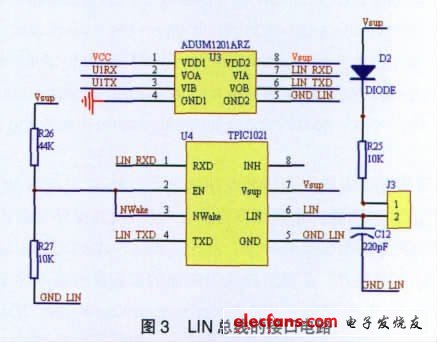
The Dspic30f4012 chip does not have a LIN bus interface, but has an SCI communication interface. In this paper, the TPIC1021 chip is selected as the SCI and LIN bus conversion chip, as shown in Figure 3. After the SCI communication pins U1RX and U1TX are electrically isolated by magnetic coupling isolation devices, they are respectively connected to LIN_RXD and LIN_TXD of the LIN driver, and after conversion, the LIN bus signal is output at the LIN pin. A magnetic coupling isolation device ADUM1201ARZ is added between the bottom controller Dspic30f4012 and the LIN transceiver TPIC1021, which is used to improve the anti-interference ability of the battery pack detection system communication and solve the problem of short circuit caused by "common ground" in distributed detection, effectively Isolate the electrical connection of each detection unit, and also isolate the bottom voltage from the upper LIN bus. When the LIN transceiver is used as the master node, the J3 jumper in Figure 3 needs to be short-circuited with a jumper pin, and when it is used as a slave node, do not jumper the jumper.
This brush is Plastic Brush. There are some kinds of plastic brushes in it. Now I will introduce some informations for you. Plastic brush is made up of ordinary plastic brush,plastic brush with small wheel and water absorption brush. Plastic brushes will increase of service life,so it will save your money. Every plastic brush has two lines of preventing ESD. They can effectively eliminate ESD and also can eliminate a large number of mites. Plastic brush is also a dual purpose brush. It not only can clean the wooden Floor,but also the carpet. So it will let your homework easily. Water absorption brush is also a plastic brush,it can sweep the floor that with some water or some liquid state thing. Its suction power is very high. Now let's see some pictures about it.


Plastic Brush
Plastic Brush, Plastic Brush, Plastic Floor Brush, Plastic Cleaning Brush
Ningbo ChinaClean Household Appliances Manufacture Co., Ltd. , https://www.chinaclean-elec.com