
Abstract : According to the characteristics of large amount of communication data and high real-time performance of UAV navigation system, a navigation system based on dual DSP is designed. One is a decoding DSP, which is used to receive terrestrial remote command, control mission equipment and handle GPS information; For the navigation DSP, used for navigation control, downlink telemetry data; dual-port RAM chip IDT70V27 is used to ensure accurate data communication between the two; GPS information is accepted through external serial port transceiver chip TLl6C752; actual flight experiments prove the system The drone's navigation tasks can be fully realized and the system is simple and reliable.
Keywords: DSP; drone; IDT70V27, TL16C752
0 Preface
With the advancement of electronic technology, sensor technology, and software algorithms, the application of drones has developed rapidly. In drone systems, the reliability and accuracy of navigation systems have played an increasingly critical role. Global Positioning System (GPS) features all-weather, high-precision location and speed information, making it ideal for small drone applications.
This article describes a dual-DSP based navigation system design method, using dual-port RAM for data exchange. At the same time, the use of external expansion serial chip TL16C752 to achieve the acceptance of GPS information, improve the interrupt level, to avoid data loss caused by communication conflicts, thus ensuring the reliability of GPS data.
1 Overall design of navigation system
The drone navigation system is mainly used for voyage estimation, fault handling, path planning, acceptance of remote control commands, and delivery of telemetry data. Therefore, there are high requirements for the accuracy and reliability of the data. According to this feature, TI's TMS320F2812 is used as a processor. It is a 32-bit fixed-point DSP chip with strong digital signal processing capabilities. Especially suitable for industrial automation control and digital signal processing and other occasions.
The system is mainly composed of navigation DSP, decoding DSP and task platform. The decoding DSP is responsible for receiving terrestrial remote control commands and GSP positioning information, and transmits the information to the navigation DSP through the dual-port RAM. The navigation DSP performs navigation calculation according to the positioning information and returns the attitude information to the ground station. The data exchange between navigation and decoding is realized through the dual-port RAM chip IDT70V27; while the acceptance of GPS data is through the TL16C752. The overall design diagram of the drone navigation system is shown in Figure 1.
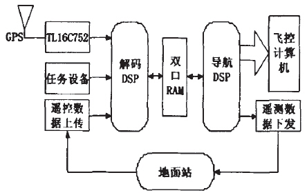
Figure 1 Overall Design of Navigation System
2 Data Exchange Implementation
2.1 Hardware Implementation
Because the navigation system needs to receive GPS positioning information in real time. And perform decoding calculations; at the same time, it must receive remote control commands from the ground station, and the amount of data processed is large. Therefore, the requirements for the stability and reliability of data communications are relatively high. Traditional data communications include serial, parallel, DMA, and dual-port RAM. Comprehensive advantages and disadvantages of various communication methods. Considering the high real-time performance and large amount of data in the navigation system, it is determined that the system uses dual-port RAM to achieve real-time data communication between the decoder chip and the navigation chip. The IDT70V27 is a high-speed 32k×16bit dual-port RAM chip developed by IDT. It allows both ports to simultaneously read and write high-speed data. Each port has its own control signal line, address line, and data line. High-speed access to data. The fastest access is also 15ns. Can be used with most high-speed processors. There is no need to insert wait states.
Dual port RAM chip and drone navigation system connection diagram shown in Figure 2.
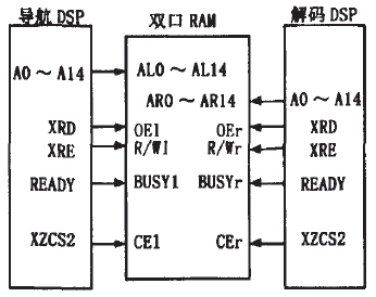
Figure 2 Dual Port RAM and Navigation System Connection Diagram
The key to using dual-port RAM is to solve the competition problem caused by the two ports operating on the same RAM unit at the same time. IDTTOV27 offers two ways to solve this problem:
(1) Interruption method. IDT70V27 has two sets of interrupt logic. Two interrupt pins, INT1 and INTr, can be connected to the interrupt input pins of the left and right CPUs respectively to implement the handshake of the CPU.
(2) Hardware arbitration mode. There is a BUSY pin on the right and left of the IDT70V27. They are: BUSYl and BUSYr. When CPUs at both ends do not read or write to the same address of dual-port RAM at the same time, BUSY1 and BUSYr are at the same time high level, and CPUs at both ends can access at the same time. When the CPUs at both ends want to access the same address, which port's request signal appears. The corresponding one-side BUSY signal is low, prohibiting its operation; and when it cannot be determined which of the CPU's request signals appears first, the dual-port RAM allows only one of the BUSY signals to be low. This will ensure that the CPU only reads and writes the low side of the BUSY signal, and the other side is disabled, thus avoiding the errors caused by the CPU competing for the same address.
Taking into account that navigation software is performed in the interrupt program, it is not convenient to perform interrupt processing. And the second way is more convenient to deal with. Therefore, the system adopts the second method.
2.2 Software Implementation
Software implementation is also the key to successful use of dual-port RAM. How to process and exchange data quickly and correctly in software design relates to the safety of drone navigation systems and even the entire drone. This paper proposes a new method to operate with a defined structure. The data exchange of the dual-port RAM can be accurately and conveniently performed. First, define a structure pointer variable to point to the chip select address of the dual-port RAM, and then define the variable name associated with it in the structure. When it is required to operate, it is only necessary to operate the structure directly. Some of the structures are defined as follows.
The data structure decoded to navigation is defined as follows:
Volatile DtoN *DTN= (DtoN *) 0x82000;
//define the structure pointer typedef struct {
Unsigned char GPS_state; //GPS status float GPS_lat; //GPS latitude float GPS_lon; //GPS longitude...
} DtoN;
The navigation to the decoded data structure is defined as follows.
Volatile NtoD *NTD = (NtoD *) 0x80100;
//define the structure pointer tepedef struct {
Unsigned char state;
Unsigned char parachot_open;
//Navigate to decoding, open the parachute unsigned int altitude; //Aircraft pressure altitude...
} NtoD;
Through the above software definition, the variables defined in the structure can be directly called in the program for data exchange.
3 GPS data acceptance and processing
The TMS320F2812 has two UART serial ports, one for receiving ground station remote commands and the other for serial communication with task devices. These two asynchronous communication serial ports have lower interrupt levels and are easily interrupted by other systems or peripherals; in order to handle GPS data more efficiently, the interrupt level is increased. The use of external 64-bit FIFO serial transceiver chip TL16C752 with the interrupt to receive and process GPS data.
3.1 Characteristics of Externally Expanded Serial Port TL16C752
The serial transceiver chip TL16C752 used in this article is a new type of UART (Universal Asynchronous Receiver and Transmitter) transceiver introduced by Tl. Its main features are:
(1) Acceptance of FIFO startup and stop can be achieved through software programming.
(2) There are two control modes: The software control mode can be implemented by programming Xon\Xoff characters; the hardware control mode can be achieved by setting the RTS and CTS pins and corresponding registers.
(3) Pin compatible with STl6C552. Built-in two UART systems can work independently.
3.2 Design of Level Conversion Circuit
Because the GPS antenna of the navigation system is output through the OEM board, the GPS data output by the OEM board is in the form of RS232 signals. Therefore, the RS232 level should first be converted into the TTL level through the level conversion chip and then input to the external expansion serial port. TL16C752. The level conversion chip adopts MAX3232 of Maxim Company, MAX3232 belongs to 3.3V power supply device, can connect with TL16C752 directly. It is also equipped with four 0.1uF capacitors and one bypass capacitor required by the internal charge pump. As shown in Figure 3.
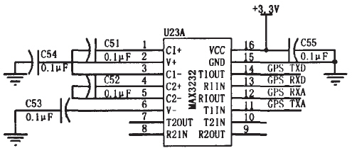
Figure 3 level conversion circuit design
Through the above circuit conversion, the output GPS signal can be connected with the external expansion serial chip TL16C752.
3.3 Interface Design of Externally Expanded Serial Port TL16C752
The operating voltage of the TL16C752 is a standard 3.3V and can be directly connected to TI's DSP. The TL16C752 is reset during software internal initialization. The chip select signal of the TL16C752 is directly connected to the ZONE0 of the TMS320F2812. The address line of the TL16C752 is directly connected to the lower three address lines of the F2812. The interrupt pin is directly connected to the two external interrupt pins of the F2812. As shown in Figure 4.
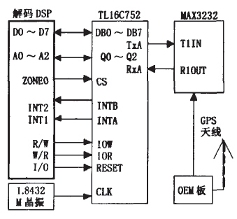
Figure 4 DSP and external expansion serial port TL16C752 connection diagram
The following is the initial software code of TMS320F2812 to TL16C752:
Volatile int *ExSCI=(int*) Ox002000;
EALLOW; GpioMuxRegs. GPEMUX. Bit. XINTl_XBI()_GPloE0=1; //The l pin of GPIOE is set to the external extended serial interrupt pin PieVectTable. XINTl=&ISRxlNT1; //external interrupt EDIS;
* (ExSCI+ExSCI_LCR)=0xBF;
//Allow to set advanced performance * (ExSCI+ExSCI_DLL)=0x06; //Low baud rate * (ExSCI+ExSCI_DLH)=0x00; //High baud rate * (ExSCI+ExSCl_EFR)=Ox10;
// Allow enhanced performance * (ExSCI+ExSCI_LCR)=0x00;
// Do not allow setting advanced performance *(ExSCI+ExSCI_MCR)=0x08;
//Allow setting TCR and TLR
* (ExSCI+ExSCl_FCR)=0x07;
// Allow use of FIFO. Clear FIFO content * (ExSCI+ExSCI_FCR)=0x01;
//Allow FIFO to be used, DMA mode is 1
* (ExSCI+ExSCI_IER)=OxO1; //Allow Interruption * (ExSCl+ExSCl_LCR)=0x03;
Asm("NOP");
PieCtrl. PIEIER1. Bit. INTx4=1;
// PIE Receive Interrupt Enable External Interrupt
3.4 Software processing of GPS data
The information that GPS's OEM board outputs includes the position, speed, and time of the drone, and the status of the satellite. Because GPS adopts ASCII code acceptance, its frame length is indeterminate. In accepting interruptions, it uses the method of verifying the frame header and frame trailer to receive and process GPS data. After entering the interrupt, first verify whether the header data is received. If the header data is received, the subsequent data is stored in the corresponding storage area, and the processing is repeated until the end of the frame is received. Such a frame of data will be received, exit the interrupt and then decode the data in the main program to get the corresponding GPS information. The flow chart of receiving GPS data is shown in Figure 5.
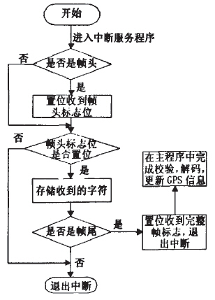
Figure 5 GPS data reception flowchart
The part of the code that receives GPS data is as follows:
While(* (ExSCI+ExSCI_LSR) &Ox01)
{
DEC_RX_char = (* ExSCI)&0x00FF;
If(DEC_RX_char=='$') //Determine header {DEC_RX_i=0;
DEC_GPS_head_flag=1;
// Set the received header flag }
If(DEC_GPS_head_flag==1)
{
DEC_msg[DEC_RX_i++]=DEC_RX_char;
If (DEC_RX_char=0x0A) //Judge the end of the frame {DEC_frm_fnd_flag=1; //Set the complete frame flag DEC_GPS_head_flag=0;
DEC_RX_i=0; }
}
}
4 Simulation results
A digital closed-loop simulation system was built to verify the navigation system. Five waypoints were designed in the electronic map. The dashed line is the design route and the solid line is the drone trajectory. It can be seen that the UAV can successfully track the planned route. . Simulation results verify the correctness and reliability of the navigation system.
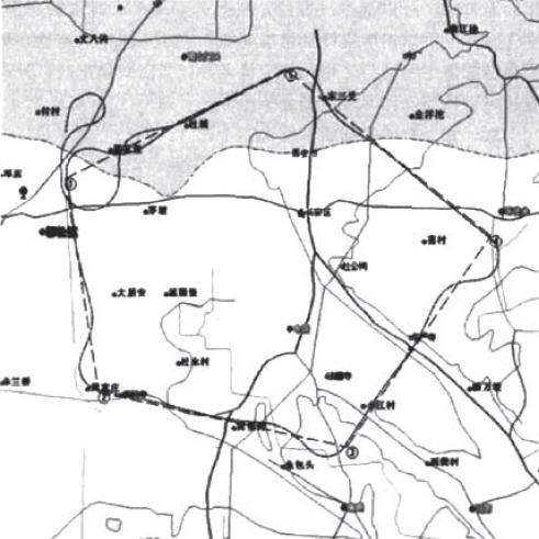
Figure 6 simulation results
5 Conclusion
This paper presents a design method of UAV navigation system based on dual DSP. The system has successfully completed the functions of the UAV navigation system. Simulation results also verify the correctness and reliability of the method. At present, the design has been successfully applied to certain types of non-inboard navigation/flight control systems, and the operation is stable and reliable.
Kids sleep headphones, specially designed for children, made of soft fabric, built-in speaker, cover your eyes while sleeping, fixed with Velcro.It connects the phone, playing music, and let you relax, help to sleep.The shape can be customized, it can be a unicorn, crocodile, chicken, duck, cow, etc., cute shape, loved by children.
Advantages:
1. Soft and comfortable sleep headphones with ultra-thin speakers.These headphones are a good choice for kids, and students who hate earbuds or bulky headphones.Lightweight, comfortable, washable headband, adjustable, earphones and headband fit perfectly.
2. Easy to carry, unique design makes it easy to track and find.
3. The headband is soft and washable. The ultra-thin headphones are almost unobtrusive and can be used while riding, without disturbing the car seat headrest.
4. Universal device, equipped with 3.5mm stereo plug or Bluetooth, can be used with all your favorite devices.

Sleep Mask With Earphones,Kids Headphones,Kids Headband Headphones,Kids Sleep Headsets
Shenzhen Linx Technology Co., Ltd. , https://www.linxheadphone.com