
In portable and miniaturized consumer products, the use of Class D audio power amplifiers has become very common. This paper introduces the design principle of the output low-pass filter of the class D audio amplifier, and gives the calculation method and the considerations of the selection of the inductance and capacitance values ​​in the filter. This article also uses National Semiconductor 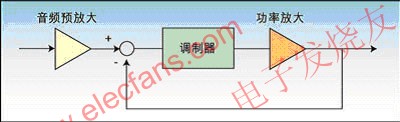
This article refers to the address: http://
Figure 1: The composition of a single-chip Class D audio amplifier.
Currently, switching mode (Class D) audio power amplifiers are common in most portable and miniaturized consumer products such as MP3, portable DVD and flat panel displays. Due to the lower power consumption of the Class D amplifier, higher efficiency can be achieved. It extends the battery life of portable devices and reduces the size of the heat sink and the area of ​​the PCB, saving system cost. Therefore, many large flat panel displays and consumer audio products are more willing to use such amplifiers.
However, Class D amplifiers are based on digital modulation techniques that use high switching frequency signals to achieve efficient amplification of the signal. The modulation frequency is typically up to hundreds of kHz, which is well beyond the audio range. Since we need to recover the desired real audio signal (music) from the digitized or modulated signal, an output low pass filter is required to filter out the high frequency components to reproduce the real analog signal that matches the human auditory system.
Here, we will elaborate some considerations and recommendations for the output low-pass filtering design.
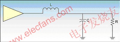
Figure 2: BTL half-circuit model.
Class D Amplifiers: Monolithic Class D audio amplifiers include analog audio inputs, modulators, power transistors, etc. (see Figure 1).
Output Filter Design: Since we need to recover the required audio signal, it is important to design an excellent output low-pass filter to filter out high frequency components (unwanted signals) and obtain high quality analog sound. We must design an output filter with a specific reactive output impedance to match the load impedance. The BTL half-edge circuit model is shown in Figure 2.
The output filter of a Class D amplifier is typically a second-order, LC-type Butterworth filter. This is because the Butterworth filter provides a relatively flat passband frequency response and requires a small number of components. Here is a reference graph showing the LPF response of the Butterworth, Bessel and Chebyshev type filters (Figure 3).
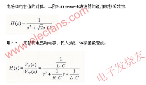

Figure 3: Comparison of low-pass filter responses of Butterworth, Bessel, and Chebyshev filters.
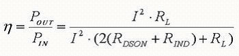
For an actual BTL circuit, the output filter is shown in Figure 4.
The derived BTL filter equation is:
According to the above equation, Table 1 lists the inductance (L) value and capacitance (C) value corresponding to the specific fc and RL.
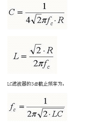
Inductor selection: In the output filter, the inductor is the key component. It is related to the DC resistance and rated peak current specifications of Class D audio power amplifier systems. The DC resistance reflects the efficiency of the total output power. The efficiency of the system can be estimated by:
Where: RL is the DC resistance of the speaker, RDSON is the transistor on-resistance of the output driver inside the Class D amplifier; RIND is the DC resistance of the inductor.
Figure 4: Actual BTL circuit output filter.
In addition to choosing the appropriate inductor value to achieve a particular cutoff frequency, the maximum DC resistance of the output inductor is another key parameter that affects overall efficiency. Therefore, it is strongly recommended to use an inductor with a lower DC resistance.
Another important parameter that must be considered for an inductor is its maximum rated current. If the inductor's rated current is not sufficient to maintain the output current of the device, the inductor will short-circuit. This will cause damage to the device or speaker due to large currents.
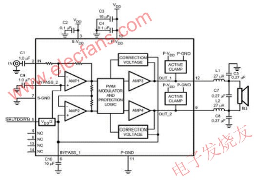
Figure 5: Application block diagram of the LM4680 (determination of the value of the LC output filter).
Finally, it is worth mentioning that in order to reduce distortion, EMI and crosstalk, shielded inductors (eg pot core inductors) are recommended.
The pot core is known for its excellent shielding performance because the inductor coil is completely surrounded by the core except for the two narrow slots used to traverse the wire.
Capacitor Selection: One of the most important parameters in evaluating high-frequency chip capacitors is Q (quality factor), or the associated equivalent series resistance (ESR).
Simply put, ESR is a measure of all series and parallel losses in a capacitor at a given frequency. In theory, the "ideal" capacitor will have an ESR of 0 Ω and is purely reactive, with no real (resistive) component. The current flowing through the capacitor will just exceed the voltage across the capacitor by 90 at all frequencies.
Economical Channel type fiberglass flexible Cable support tray Application
- Frp Cable Tray is Universally used in petroleum industry, chemical industry, electronic plant
- FRP Cable Tray is Suitable for some environment with high corrosion
- Modern factories and buildings with high floors
-
Any environment that need to be closed
Economical Channel type fiberglass flexible Cable support tray:
FRP cable tray is consists of a ventilated or solid bottom contained within longitudinal side members. Provides moderate ventilation with added cable support frequency and with the bottom configuration providing cable support every 4 inches. Available in metal and nonmetallic materials. Generally used with control and instrumentation cables in moderate heat generating applications with short to intermediate support spans of 5 feet to 12 feet. FRP cable tray bottom is available in flat sheet or corrugation that is 3 times stronger and 21 times stiffer than flat sheet bottoms. Corrugated seams between jointing sections eliminate need for bottom seam splices. Load Depths: 3" through 5-1/2" Materials available: Aluminum, hot-dipped galvanized Steel,Stainless Steel or figerglass.
Outdoor Cable Tray,C Channel Cable Tray,Aluminum Alloy C Channel Tray,Channel Type Cable Tray
Jiangsu Loncin Electrical Equipment Co.,Ltd , https://www.loncincabletray.com