
Abstract: Taking the "Freescale" Cup Smart Car Competition as the research background, MC9S12XSl28 is used as the core processor. By comparing the performance of different design schemes of each module, the design and implementation of smart car power supply, drive, image acquisition and speed measurement are completed. . The assembly and mechanical adjustment of the smart car were completed through a large number of experimental adjustments, making the structure of the smart car more reasonable. The experimental and actual game performance shows that the smart car has a stable hardware structure and good performance.
Key words: power supply design; motor drive; image acquisition; binarization circuit; MC9S12XSl28
This article refers to the address: http://
With the rapid development of the automotive electronics industry, smart cars, as the combination of the latest technological achievements such as electronic computers and the modern automobile industry, have become the focus of research because of their intelligent characteristics. The "Freescale" Cup National College Student Smart Car Competition is produced in this context, and the rules of the competition stipulate. The car can drive autonomously on the set track and win in the shortest time. Therefore, the smart car hardware is constantly innovating to meet the speed requirements of the car. In this paper, MC9S12XSl28 is used as the core processor, and the circuit design schemes of each module of the smart car are compared through experiments, so that the hardware circuit with stable performance is designed. The actual performance of the contest is good and stable.
1 system overall design
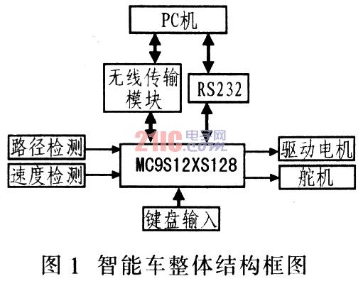
1.1 Intelligent car function design According to the rules of the competition, the smart car should have the functions of path identification, direction control, speed control and status detection. The design uses the Freescale 16-bit microcontroller MC9S12X-Sl28 microcontroller as the core control unit. The CCD camera is used as the sensor for identifying the path, and the I/O port of the MC9S12XSl28 MCU is processed to control the motion decision of the car. At the same time, the internal ECT module sends a PWM wave to drive the DC motor and the steering gear to control the speed and steering of the smart car. In order to accurately control the speed of the car, a photoelectric encoder is installed on the rear axle of the smart car to collect the pulse signal of the wheel speed. After the MCU captures, the PID automatic control is performed to complete the closed-loop control of the speed of the smart car. The principles to be noted in the design: the center of gravity is as low as possible, the volume is as small as possible, the drive is as large as possible, and the structure is as simple as possible.
1.2 System overall structure The hardware design of the smart car is the basis of the whole system design. Only under the premise that the system hardware design is feasible, stable and reliable, other control solutions can be continued. The system hardware mainly includes single chip microcomputer (master control), CCD camera (image acquisition), rotary encoder (speed detection), SD card (large data storage), wireless meter reading (data wireless transmission and reception), DC motor (speed control), Servo (direction control), power supply (5 V/6 V/7 V/3.3V/9 V/12 V), vehicle model, driver MC33886, MOSFET tube, etc. Figure 1 is a block diagram of its overall structure.
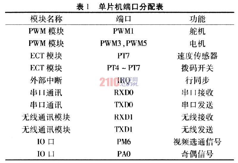
1.3 MC9S12XSl28 MCU Introduction This design uses Freescale MC9S12XSl28 microcontroller as the control unit. The system board has MCU core system, supports serial port debugging and downloading, has an extended interface, can be developed twice, and supports μCOSII. This development board is highly compatible, and the monitoring program is powerful, providing various basic development and debugging functions, such as downloading and running programs, breakpoint settings, and memory display. The MC9S12XSl28 Flash online programming technology can also be used to write online user programs and modify Flash storage content at any time. Simultaneous online real-time simulation and monitoring of self-programming. The controller internal unit is allocated according to the actual design needs, as shown in Table 1.
2 Design and implementation of each functional module The intelligent vehicle hardware system mainly includes power supply, motor drive, speed measurement, steering gear, image acquisition and processing.
2.1 Power module design According to the design requirements of the smart car, it is necessary to provide 5 V power supply for the single chip microcomputer, SD card, speed measuring module, PCB board circuit, wireless communication module, etc.: 6 V power supply steering gear, CCD camera needs 12 V Working voltage. The difficulty is the 12 V DC-DC boost circuit. Here, the MC34063A is used to build a boost circuit that is boosted from 7.2 V to 12 V. The MC34063A is a monolithic bipolar linear IC designed for DC-DC converter control with a built-in duty cycle control oscillator, driver and high current output switch for 1.5 A switching current. It can form a switching boost converter, a buck converter and a power inverter with a minimum of external components. Figure 2 is a schematic diagram of a DC-DC boost circuit.

2.2 Motor and steering gear drive module design The most critical factor affecting the speed of a smart car is the driving force. The "driving force" includes not only the drive motor but also the motor drive circuit. The motor drive circuit should provide powerful power for the car, and its own power consumption should be small, which can ensure that it will not heat up and continue to work stably under the condition of long time and high current output.
According to the performance index of the PWM speed motor drive circuit. In the actual production process, the following two schemes are mainly used: 1) using MC33886 cascade to form a driving circuit; 2) using a MOSFET to build an H-bridge circuit.
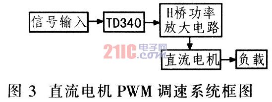
Considering that the MC33886 has limited output current and cannot provide a relatively strong driving force, the H-bridge driver circuit built by MOSFET is designed independently. Net 3 is a block diagram of the DC motor PWM speed control system. The TD340 and MOSFET tubes form an H-bridge drive circuit. The TD340 is an N-channel power MOSFET tube driver. Suitable for DC motor control.
Through experiments to compare the circuit acceleration, braking and frequent braking ability of the two schemes, it is found that the two circuits have their own characteristics. MC33886 cascaded drive circuit drive current rises fast, suitable for braking, but energy consumption is large and stable current is small; while MOSFET tube start braking is slow, but the drive current is large, suitable for straight road driving, low power consumption. Considering the energy consumption problem, the MOSFET tube driving method is adopted in the actual car design.
The steering gear is used to control the steering of the front wheels and cooperate with the driving motor of the rear wheels to enable the vehicle body to travel freely. On the smart car, the output angle of the steering gear is controlled by the connecting rod drive to control the front wheel steering. The output angle of the steering gear is between -45° and +45°. Before using, the duty ratio of the PWM wave corresponding to each angle must be measured.
2.3 Speed ​​measuring module design As an important part of realizing the photoelectric control of the closed-loop control of smart cars, the speed measuring function is indispensable. Commonly used speed measuring methods are photocell speed measurement and photoelectric encoder speed measurement.
Practice has proved that the phototube detection method is low in cost and easy to implement. However, the accuracy is low, the reliability is poor, and it is easily affected by ambient light. When the vehicle speed reaches 3 m/s, the detection will cause problems. Although the cost of using the photoelectric encoder is high, the precision is high and the stability is good. Therefore, considering the comprehensive consideration, the photoelectric encoder is used to detect the motor speed.
The E6A2-CS100 photoelectric encoder manufactured by OMRON is used. It is powered by 5 to 12V DC, and the speed sensor is connected to the motor through the gear on the rear axle. The wheel rotates 2.75 turns per revolution of the wheel.
2.4 Image acquisition and processing module design For the actual environmental conditions of smart car competition, commonly used image data acquisition methods are: A/D conversion acquisition method and hardware binarization method of comparator.
The A/D conversion time of the MC9S12XSl28 MCU is as short as 7μs without overclocking. If a camera with a resolution of 320 lines is selected, the single-line video signal lasts for about 20 ms/320=62.5μs, A/D converter. The number of points sampled for a single line of video signal will not exceed (62.5/7) +1 = 9. If a camera with a resolution of 640 lines is used, the single-line video signal lasts for about 20 ms/640=31 μs, and the A/D converter will not sample more than (3l/7)+l=5 for single-line video signals. One. It can be seen that the higher the resolution, the shorter the duration of a single-line video signal, and the fewer points that the A/D converter can sample for a single-line video signal. As mentioned above, the higher the resolution of the camera, although it can improve the vertical resolution, it will reduce the number of points of the single-line signal of the single-chip A/D sampling and weaken the horizontal resolution.
The resolution of the camera is usually above 300 lines, so the duration of a single-line video signal is up to 20 ms/300=66 μs, then the A/D sampling has the most points (66/7) +1=10 per line of video signals (no overclocking). ), this does not meet the requirements of the car positioning. Therefore, when using A/D to capture images, the camera resolution should not be too high. In order to ensure the accuracy of the image points and leave more time for image processing, the comparator is used to implement binarization instead of A/D sampling method to achieve data acquisition.
3 Conclusions The hardware circuit design of the national smart car race car was completed around the MC9S12XSl28 MCU. Through experiments to compare the characteristics of each module circuit, choose a better performance program. The processing of image acquisition and binarization of the CCD camera is completed by the hardware binarization circuit, which saves the time of micro processing. By comparing the performance of the two commonly used drive circuits, the circuit suitable for the smart car race is selected. Experiments show that the whole car has good driving performance, fast image acquisition and stable driving. The smart car performed well in the smart car competition.
With input voltage 100-240V22V, our 22V AC Desk-top power supply can be used in every country in the world,in LED lighting, stage lighting, security, video game player and other products. Normally, there are 3 different kinds of AC sockets for a Desktop Power Adapter – they are C6 AC socket, C8 AC socket and C14 AC socket. All our AC/DC power adapters were get through 100% full-load burning test for at least 2 hours, and 3000Vac withstanding voltage test for 1 minutes. The conversion rate of our desktop power supplies is 85%, which is much higher than other factories.
22V Desktop Switching Power Supply
22V Desktop Switching Power Supply,22V Switching Power Supply,22V Power Supply
Shenzhen Juyuanhai Electronic Co., Ltd. , http://www.powersupplycn.com