
The peak current mode controlled non-continuous buck-boost converter is a good choice for LED drivers, although the output voltage may be higher or lower than the input voltage. However, when using this buck-boost converter to design a driver, a change in LED voltage will change the LED current, and an open LED will cause an excessive voltage at the output, which will damage the converter. This article discusses the converter design for LEDs in detail and presents a number of ways to overcome its inherent shortcomings.
Light-emitting diodes (LEDs) have been used for many years, and as the latest technology advances, they are becoming strong competitors in the lighting market. The new high-brightness LEDs have a long life (about 100,000 hours) and high efficiency (about 30 lumens per watt). Over the past three decades, the light output brightness of LEDs has doubled every 18 to 24 months, and this growth will continue. This trend is called Haitz's law, which is equivalent to the Moore's Law of LEDs.
Electrically, LEDs are similar to diodes in that they are also unidirectionally conductive (although their reverse blocking capability is not very good, high reverse voltage is easily damaged (LED) and has low dynamics similar to conventional diodes. Impedance VI characteristics. In addition, LEDs generally have a rated current when they are safely turned on (high-brightness LEDs are typically rated at 350mA or 700mA). When rated current is used, the LED forward voltage drop may be quite different, usually 350mA white light. The voltage drop of the LED is between 3 and 4V.
Driving the LED requires a controlled DC current. In order to make the LED have a longer service life, the ripple in the LED current must be low, because the high ripple current will cause the LED to generate large resistive power consumption and reduce the LED life. LED drive circuits require higher efficiency because the overall efficiency depends not only on the LED itself but also on the drive circuit. Switching converters operating in current-controlled mode are ideal drive solutions for high power and high efficiency requirements in LED applications.
Driving multiple LEDs also requires careful consideration. Figure 1 is a series-parallel connection circuit of LEDs. 1(a) is a parallel connection circuit of LEDs. Figure 1 (h) is a series connection circuit of LEDs. Since the dynamic impedance and forward voltage drop of each LED are not the same, if there is no external current sharing circuit (such as current mirroring), it is impossible to ensure the same current flowing through the LED; in addition, the LED string will be caused by the failure of one LED. Disconnected, causing all of the LED current to be distributed between the remaining LED strings, which will cause the current on the LED string to increase, potentially damaging the LED. Therefore, for the above two reasons, the parallel LED circuit as shown in Fig. 1(a) is generally not used in design.
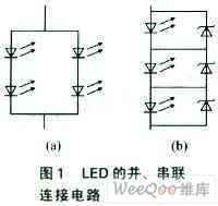
Therefore, it is better to connect the LEDs in series. The disadvantage of this method is that if one LED fails, the entire LED string will stop working. A simple way to keep the remaining LED strings working is to connect a Zener diode (which has a voltage greater than the highest voltage of the LED) in parallel with each (or each) LED, as shown in Figure 1(b). Thus, after any LED fails, its current will flow to the corresponding Zener diode, and the rest of the LED string will still work normally.
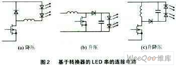
The basic single-stage switching converters can be divided into three categories: buck converters, boost converters, and buck-boost converters. When the voltage of the LED string is lower than the input voltage, Figure 2(a) is the ideal choice for the buck converter; when the input voltage is always lower than the string output voltage, the boost converter is more suitable. Figure 2(b) When the output voltage may be higher or lower than the input voltage (caused by the output or input change), it is appropriate to use the buck-boost converter as shown in Figure 2(c). The disadvantage of boost converters is that any transient in the input voltage (which can cause the input voltage to rise above the output voltage) can cause a large current flow on the LED (due to the low dynamic impedance of the load), which can damage the LED. The buck-boost converter can also replace the boost converter because transients in the input voltage do not affect the LED current.
The working principle of the buck-boost converter
For LED drivers in low voltage applications, buck-boost converters are a good choice. The reason is that they can drive LED strings (boost and step-down) with voltages above and below the input voltage, high efficiency (easy to reach more than 85%), and discontinuous operation mode can suppress input voltage changes (provided Excellent line voltage regulation), peak current control mode allows the converter to regulate LED current without complex compensation (simplified design), easy linear and PWM LED brightness adjustment, switching transistor failure without damaging the LED, and more. Figure 2 shows the connection of the buck, boost and buck-boost converter to the LED string.
However, this method still has disadvantages: First, the peak current control problem, because the buck-boost converter using the discontinuous current mode is a constant power converter. Therefore, any change in the LED string voltage will cause a corresponding change in the LED current; another problem is that the LED open state will create a high voltage in the circuit that would damage the converter; in addition, an additional circuit is needed to convert the constant power converter to a constant Current converters and need to protect the converter from no load.

Figure 3 shows a specific buck-boost converter application circuit with an internal oscillator for setting the switching frequency. At the beginning of the switching cycle, Q1 turns on. Since the input voltage VIN is applied to the inductor, the inductor current (iL(t)) begins to rise from zero (initial steady state). When the induced current rises to a preset current value (ipk), Q1 turns off. The switch on time (ton) is determined by:
Ton=ipkL/VIN
At this point, the total energy (J) stored in the inductor is:
J=Li2pk/2
Thus, although the switch will be turned off at this time, the current flowing through the inductor will not be interrupted. This turns diode D1 on and produces an output voltage (-Vo) across the inductor, which causes the inductor current to drop rapidly. After a certain period of time tOFF, the inductor current tends to zero. This time can be calculated by the following formula:
tOFF=ipkL/VO
In order for the converter to operate in discontinuous conduction mode, the sum of the switch on time and the inductor current fall time must be less than or equal to the switching period TS to ensure that the inductor current can start from zero during the next switching cycle.
In fact, in the case of the minimum input voltage and the maximum output voltage, (tON+tOFF) can obtain the maximum value. Therefore, ensuring that the converter operates in discontinuous conduction mode at these voltages ensures that the conditions listed in the following equations are met under all conditions: tON+tOFF≤Ts
The product of the energy in the power (Pin) inductance obtained by the converter from the input and the switching frequency f: ie:
Pin=fsLi2pk/2
Assuming that the voltage (VO) of the LED string is constant and the efficiency is 100%, then the current (iLED) of the LED is:
iLED=PIN/VLED=Li2pkfs/2V
In peak current control mode, ipk is usually a fixed value. Therefore, the LED current is completely independent (theoretically) at the input voltage. At a fixed ipk, the rise (fall) of the input voltage causes the transistor's turn-on time to decrease (increase) in inverse proportion, which provides good line voltage regulation. In practical applications, the delay between the detection of the current peak and the actual turn-off of the GATE pin by the control IC can cause a change in input power. Shorter on-times can cause more errors due to delay times, as the delay time will account for a significant portion of the turn-on time.
In fact, the LED current is inversely proportional to the voltage of the LED string. A circuit with a nominal output of 20 V and 350 mA will generate 700 mA at 10 V output, which is clearly not the desired result. However, by making the switching frequency proportional to the output voltage, the above equation provides a method of converting a constant power converter to a constant voltage converter.
Assuming fs=KVO, where K is a constant, then there are:
iLED=kLi2pk/2
In this way, the iLED will be independent of the input and output voltages.
Another disadvantage of the flyback converter is that it is susceptible to the open state of the output. When the LED is open, the energy stored in the inductor is transferred to the output capacitor at the end of each switch on-time. Thus, a load that lacks a capacitive discharge will cause the voltage across the capacitor to gradually rise, eventually exceeding the nominal value of the device and damaging the power stage. Therefore, output voltage feedback and overvoltage protection can be provided by adding additional circuitry.
Output voltage feedback
Figure 4 is an additional circuit that provides overvoltage protection and LED open circuit protection. In fact, many peak current mode controller ICs have dedicated RT pins. A resistor connected to this pin can be used to set the internal current, and its internal current is used to charge the oscillator capacitor (which can be internal or external). The ramp voltage on the oscillator capacitor controls the switching frequency so that the switching frequency is proportional to the output current of the RT pin. The smaller the resistance (large), the larger the current (small) and the higher the switching frequency (lower). Based on this principle, the output voltage feedback can be used to adjust the switching frequency.
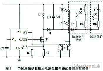
In the circuit shown in Figure 4, resistors R3 and R4 form a voltage divider. The voltage across R4 minus the voltage drop (Vbe) between the base and emitter of transistor Q2 is the voltage across R5. Therefore, the current flowing through R5 (IR5) is:
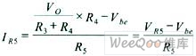
This current is obtained from the pin RT of the control IC using a matched pair of transistors.
Resistor R2 in Figure 4 is used to start the converter. In the startup state, the output voltage is zero and IR5 is also zero. The converter does not start because there is no current from the controller RT pin. Increasing resistor R2 can get a small amount of current in the startup state and make the size of R2 meet:
IR5>>V(RT)/R2
Where V(RT) is the voltage on the RT pin of the controller. Satisfying this condition ensures the startup of the converter and minimizes the error caused by R2. If R3=R4 is selected, then there are:
IR5>>VO/2R5
It is assumed here that the output voltage is much larger than the base-emitter voltage drop of Q2.
Thus, according to the above formulas, the output LED current can be obtained as:
iLED=KICLi2pk/(2×2R5)
In this way, the LED current will no longer be determined by the input or output voltage. Overvoltage protection is added by resistor R6, transistor Q3, and Zener diode D2. In the open state of the LED, when the switch is turned on, the inductor stores energy, and when the switch is turned off, the energy is transferred to the output capacitor. Because there is not enough load for the capacitor to discharge, the output voltage will gradually increase every cycle. When the voltage rises above the turn-on voltage of the Zener diode, the Zener diode branch circuit consisting of D2 and R6 begins to conduct. This also provides a path through the base current of Q3 to turn Q3 on. At this time, the resistor R4 is actually short-circuited. Therefore, the PN junction of the base emitter of Q2 will be turned off, resulting in zero current on R5. This will stop the internal oscillation of the controller until the output voltage drops below the Zener diode voltage and the above process continues. This burst mode minimizes the average power of the LED in an open state. This overvoltage protection method will force the IC to enter a low frequency, low power mode of operation.
The current on the Zener diode resistor branch circuit must be capable of generating a sufficiently large voltage across R6 to bias the PN junction between the base and emitter of the transistor.
Conclusion
In a switched Led Driver with output current feedback, feedback compensation is typically also required to stabilize the converter and regulate the current to achieve the desired current value. The transient response performance of these feedback schemes is limited and does not meet the fast on/off transient response required for LED brightness adjustment of the LED. However, the converter described herein does not require any feedback compensation. The only feedback information used by this control scheme is to obtain the peak current flowing through the MOSFET through the sense resistor. Because the converter stores the required energy every cycle, it can respond instantly to transients. Therefore it can easily work with the PWM brightness adjustment scheme.
The buck-boost converter is an effective solution for low DC voltage input LED drivers that can drive LED strings regardless of whether the output voltage is above or below the input voltage. In addition, small and inexpensive additional circuitry can be added to the converter to overcome problems in load regulation and no load conditions. The converter is easy to implement and does not require feedback compensation during peak current mode control. Its open-loop characteristics make it an ideal choice for applications that require PWM dimming.
:

Fahold, a 8 year old company brings light power to your life by illuminating your offices, factories, warehouses, shopping malls, airports, etc. with its high quality LED Linear lighting products and solutions. LED Linear lighting springs out few years ago, we see the power of the linear lighting solutions, so over the years, we have been innovating our 230Vac To 24Vdc Power Supply, 24V Ultra Slim Led Driver, 12V Led Power Supply 5a driver for these type products to give you healthy low carbon environment with low energy consumption.
Application: LED Light boxes, led linear lights, led troffer ect.
Parameter:
Input Voltage:100-277V
Output voltage: 12V / 24V/36V/48V
Current: 1.6A /2.2A /2.5A /2.7A /3.3A /4.1A /5A /8A
Power factor: >0.95
THD: <15%
Dimming: 0-10V/PWM/RX/Dali
What's the benefits of Fahold Driver?
- Standard Linear Lighting
- Cost-effective led driver solution for industry,commercial and other applications
- Good quality of led driver with high efficiency output to meet different requirements
- Easy to order and install,requiring less time,reducing packaging waste and complexity
- Flexible solution
FAQ:
Question 1:Are you a factory or a trading company?
Answer: We are a factory.
Question 2: Payment term?
Answer: 30% TT deposit + 70% TT before shipment,50% TT deposit + 50% LC balance, Flexible payment
can be negotiated.
Question 3: What's the main business of Fahold?
Answer: Fahold focused on LED controllers and dimmers from 2010. We have 28 engineers who dedicated themselves to researching and developing LED controlling and dimming system.
Question 4: What Fahold will do if we have problems after receiving your products?
Answer: Our products have been strictly inspected before shipping. Once you receive the products you are not satisfied, please feel free to contact us in time, we will do our best to solve any of your problems with our good after-sale service.
Constant Voltage Led Driver
24Vdc Power Supply,24V Ultra Slim Led Driver,12V Led Power Supply
ShenZhen Fahold Electronic Limited , http://www.fahold.com