
1 Introduction The increasing awareness of people's health and environmental awareness has caused increasing attention to environmental parameters and their impact on the body. However, in real life, people are often surrounded by harmful gases such as gas, cigarettes, alcohol, etc., but because there is no suitable measuring instrument or because the professional measuring instrument is too expensive, it is not convenient to know the various parameter values ​​in the surrounding environment. Therefore, it is impossible to know whether environmental parameters pose a hazard to the body or the environment. Here is a design method of a multi-functional environmental measuring instrument, which is cheap, practical, portable, and has various functions such as voice broadcast measurement values ​​and harmful gas over-limit alarms.
This article refers to the address: http://
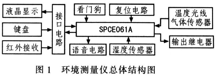
2 Overall structure and working principle The measuring instrument takes the Lingyang 16-bit single-chip microcomputer SPCE061A as the control core, and the environmental information amount obtained by the light, temperature, humidity and gas sensors is converted into an analog electric signal, which is converted into corresponding by the A/D converter. The digital signal is then processed by the CPU; the CPU calculates the measured value in real time and sends the result to the LCD display for simultaneous voice announcement.
It has a keyboard, infrared receiver circuit, manual reset and automatic power-on reset, and a hardware watchdog circuit. SPCE061A has A/D and D/A conversion modules inside, which can easily realize analog/digital conversion and voice broadcast function. The overall structure of the system is shown in Figure 1.
3 hardware circuit design
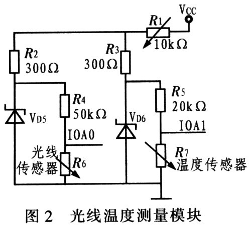
3.1 Temperature light module Temperature sensor adopts R450 type negative thermal resistance, light sensor adopts high sensitivity photoresistor, the temperature sensor and light sensor linearize better, especially in indoor environment, and the resistance value changes with the external physical quantity. Therefore, the intermediate amplifying circuit can be omitted and directly connected to the port of the single chip microcomputer 10A. The light temperature measurement module circuit is shown in Figure 2. The entire circuit is powered by a 6 V battery, and a 2 V Zener diode provides a 2 V reference for the A/D converter circuit. Adjustable resistor R1 is used to calibrate the reference voltage drop caused by temperature drift and power supply voltage drop. R4 is connected in series with R6. The change of light intensity is reflected by the change of wind partial pressure value and input to the IOAO port of the MCU for A/ D conversion. The IOA port is set to the floating input port. The variable iLM is defined in the MCU. The voltage data obtained by the light measurement is stored in the iLM, and the light is judged to be too strong, too weak or soft according to the iLM. The A/D conversion data is taken once every 1 ms, and a total of 10 times is taken to obtain data in one cycle of natural light of 100 Hz. Take 10 measurements and look up the table to get the light intensity. Temperature measurement is basically the same as light measurement. The circuit principle of this module is shown in Figure 2.
3.2 Gas Measurement Module The new semiconductor gas sensor TGS2600 is sensitive to the odor of low-concentration pollutants in the air, such as low-concentration cigarette contaminants and other odors in the air, and has high sensitivity to H2 and CO. The sensor can detect several ppm levels of H2, and the basic measurement circuit of the sensor is shown in Figure 3. This sensor requires two voltage inputs: heater voltage VH and circuit voltage VC1. A heater voltage VH is applied to the integrated heater to maintain the sensor at a particular optimum sensing temperature. The circuit voltage VC1 is loaded to facilitate measurement of the load resistance voltage Vout in series with the gas sensor. The output voltage is directly input to the MCU through the IOA4 port for A/D conversion.

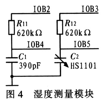
3.3 Humidity measurement module Since the humidity sensor HS1101 is capacitive, it is not possible to directly read the capacitance value of the humidity sensor HS1001, but the operating frequency of the RC circuit where the HS1 101 is located can be measured by the feed-back function of SPCE061A. It is possible to calculate its capacitance value. In order to reduce the error, a fixed capacitor C6 and a resistor Rs are used to form another feedback circuit as a reference for the humidity sensor HS1101, as shown in FIG. According to the parameters in Figure 4, in order to make the operating frequency of the humidity sensor HS1101 as close as possible to 10 kHz, select a 620 kΩ resistor and HS1101 to form Feedback1; a capacitance of 390 pF as a reference and another 620 kΩ resistor to form Feedback2.
3.4 Infrared Transmitting and Receiving Module Infrared transmitting and receiving adopts 38 kHz carrier, which has the characteristics of low power consumption, anti-interference and long distance. A separate remote control allows people to control the tester's broadcast, power on and off functions from anywhere in the room. The transmitter consists of a Sunplus 61 board and an infrared transmitting circuit. The main program calls the keyboard scanner to read the key value. If the KEY1 key is pressed, the KEY1 transmitting program is called, and the transmitting sequence is binary 1000 0000; when the KEY2 key is pressed, the transmitting sequence is 1000 0001; when the KEY3 key is pressed, the transmitting sequence is 1000 0010. . The receiving circuit inputs the MCU through the IOA7 port. The main program scans the IOA7 port after each measurement to see if there is a low-level start signal, and if so, continues to receive, otherwise the main program continues to execute downward. If the system receives a KEY1 key transmission sequence after power-on. Then, the measurement display is started; if the KEY2 key transmission sequence is received, the current temperature light humidity value and the harmful gas concentration value are broadcasted. The KEY3 key puts the system to sleep to reduce power consumption.
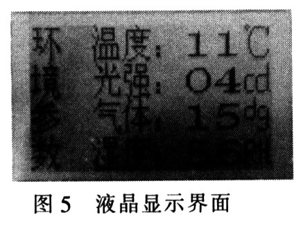
3.5 Keyboard display unit The display unit selects 128x64 character dot matrix liquid crystal display SPLC501 module assembly, which is mainly composed of LCD display, LCD control board and bias generation circuit. The current temperature value, light intensity, harmful gas concentration, humidity and other information are sequentially displayed in 4 rows, as shown in FIG. The keyboard module is mainly used to set the alarm threshold. The KEY1 key is the OK/Cancel function, the KEY2 key is the up-conversion function, and the KEY3 key is the down-regulation function. When the KEY1 button is pressed, the temperature value will continue to flash. Press KEY2 or KEY3 to set the temperature threshold. After setting the KEY1 button again, the light intensity value will flash continuously. Set the light intensity threshold and press the same. The method sets the gas concentration and humidity threshold. When the setting is completed, the button is stopped. After 2 s, the system automatically restarts the measurement.
4 Software Design The software adopts the modular design method, which consists of subprograms such as main program and keyboard processing, data acquisition, alarm, voice, liquid crystal display and infrared receiving. The main program flow of the system is shown in Figure 6. The program is the core of control and management. After the system is powered on, it is initialized. After the system is completed, the system starts normal operation, and the parameters of the environment are displayed and judged to exceed the alarm. Then the detection is performed. Infrared reception has signal input and performs functions such as display and voice broadcast.

The system temperature reminder upper limit is 27 ° C, the lower limit is 16 ° C, the light intensity is divided into 20 levels, the light below 7 is too weak, the 16 or above is too strong, too weak and too strong will have a voice reminder. The concentration of harmful gases is divided into 100 levels, and the level below 20 is harmless. The system will not alarm. At least level 20 systems will continue to voice reminders until the gas concentration drops below level 20. When the humidity is below 40%, it will not be reminded. When the humidity is above 40%, the system will remind you intermittently. The gas broadcast is set to the highest priority in the sub-programs of the four voice broadcast reminders, because harmful gases are the most harmful to the human body and most prone to accidents. In addition, there is a relay output interface outside the system, which can control external emergency equipment, such as exhaust fans, lights, humidifiers and other equipment. According to the requirements of different environmental parameters in different regions, the system's simple and easy parameter setting function can meet various environmental requirements, such as vegetable greenhouses and factory workshops. The system compilation environment is unSP IDE 2.0, which is written in assembly language and C language. The related underlying programs such as interrupt service program, A/D conversion and liquid crystal display are written in assembly language, and the rest are like measurement programs and voice broadcasts. The program is completed in C language and the program size is about 22 KB.
5 Conclusion The prototype was developed according to the above principle. The whole system consists of five modules: measurement, relay output control, battery power supply, infrared remote control and display. After actual testing, the system has a very sensitive detection and alarm capability for cigarettes, methane and alcohol, and the temperature, humidity and light are also measured to meet practical requirements. The measuring instrument can change the set value according to requirements, and is suitable for environmental measurement and safety alarms in homes, greenhouses and public places. With the improvement of people's quality of life requirements, this multifunctional portable tester will have a wider range. Application prospects. The innovation of this design is the integration of indoor environment and security alarm. The liquid crystal display and voice broadcast are very user-friendly. In addition, the infrared remote control function makes it more convenient to use.
Water Tank,Water Storage Tank,Ro Water Tank
Water Softener,RO System,Water Filter,RO Parts Co., Ltd. , http://www.cnroparts.com