
The fifth chapter delves into the in-depth explanation of AMetal. The content covers sections 5.3, which discusses the keyboard scanning interface, and 5.4, focusing on the PWM interface.
5.3 Keyboard Scanning Interface
>>> 5.3.1 Single Independent Button
1. Button Behavior
As shown in Figure 5.1, there are three main states for a button: no press, pressed, and released. A flag called ret_flag is used to differentiate between these states, with values 0xFF (invalid), 0 (pressed), and 1 (released). It's also possible for an error trigger to occur, which may result in ret_flag being set to 0xFF as well.
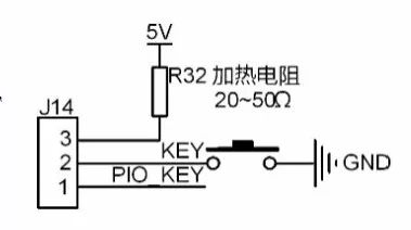
Figure 5.1: Independent Button Circuit Diagram
Since a button press typically lasts for hundreds of milliseconds, it's not necessary to continuously monitor it. Instead, it's sufficient to check the GPIO level at specific intervals, such as every 10ms. The detection method works as follows (1 indicates high level, 0 indicates low level):
(1) When no key is pressed, PIO0_1 is 1 due to its internal weak pull-up resistor.
(2) When the KEY is pressed, PIO0_1 becomes 0. After a 10ms debounce delay, if PIO0_1 is still 0, it confirms a valid key press, and the ret_flag is set to 0 to trigger the corresponding action. If it returns to 1, it's considered an error.
(3) When the KEY is released, PIO0_1 goes from 0 back to 1. After another 10ms debounce, if it remains 1, it indicates a valid release, and ret_flag is set to 1. If it returns to 0, it's considered an error.
To ensure accuracy, the GPIO state should be scanned every 10ms regardless of whether a key is pressed or not. The current key value (key_current_value) is compared with the previous scan’s value (key_last_value) to eliminate false triggers. This comparison ensures that only consistent readings are considered valid.
2. GPIO Status
GPIO can be in one of four states: 1/1, 1/0, 0/0, and 0/1. During initialization:
Key_last_value = 1, key_final_value = 1, ret_flag = 0xFF
Here, "1" and "0" represent the current and previous key values after each scan, respectively. The ret_flag is reset to 0xFF on each scan.
(1) 1/1: No change in GPIO state (no key pressed).
(2) 1/0: GPIO transitions from 1 to 0 (button pressed). After a 10ms debounce, if it remains 0, the key is considered pressed.
(3) 0/1: GPIO transitions from 0 to 1 (button released). After a 10ms debounce, if it remains 1, the key is considered released.
3. Related Functions and Examples
Board-level initialization and independent key scan functions are detailed in Listing 5.42.
Listing 5.42 Independent Key Scanner (key1.c)
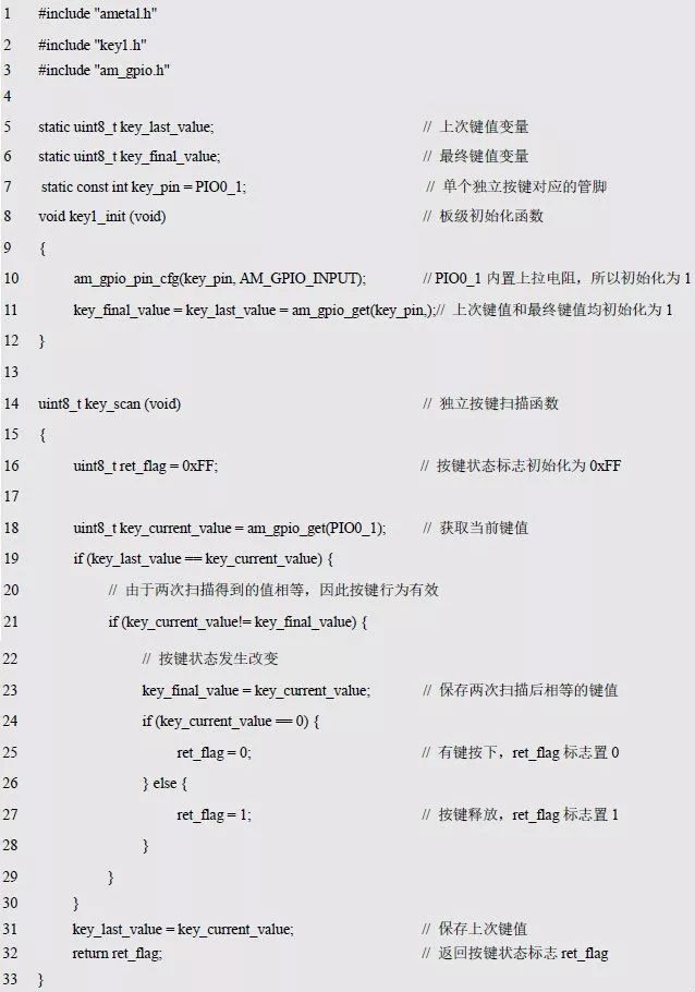
This code avoids using loops for continuous scanning, thereby improving MCU efficiency. To make it easier to use, key1.c can be wrapped into a header file, key1.h, as shown in Listing 5.43.
Listing 5.43 key1.h File Contents
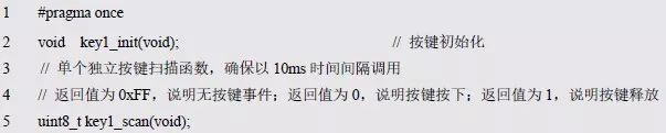
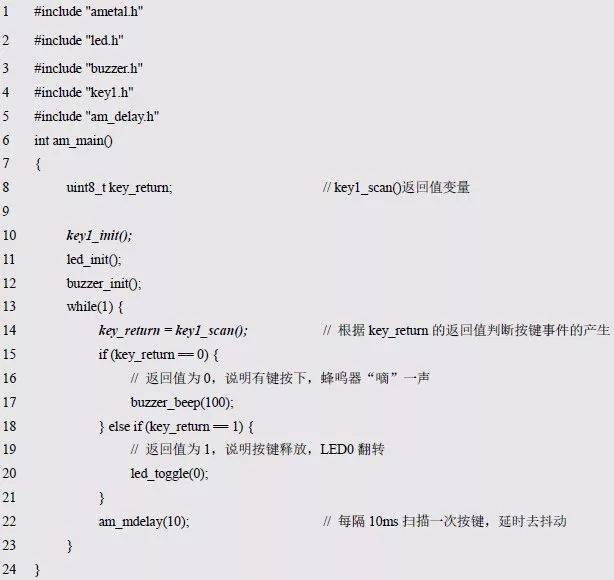
If the return value of key_scan() is 0, a key is pressed; if it is 1, the key is released; and if it is 0xFF, no key is pressed. A sample test program is provided in Listing 5.44, where a buzzer beeps when a key is pressed, and LED0 toggles when the key is released.
Listing 5.44 Independent Key Sample Program
>>> 5.3.2 Multiple Independent Buttons
The principle of scanning multiple independent buttons is similar to that of a single button. Each button uses a separate bit in a variable to represent its state. For example, a 1 in a bit represents a pressed state, and a 0 represents a released state. The levels corresponding to the pins are stored in an array of structures for each button.
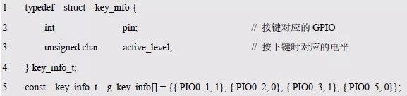
In the code segment above, four buttons are defined on PIO0_1, PIO0_2, PIO0_3, and PIO0_5, with respective levels of 1, 0, 1, and 0. The structure array contains information about each button.

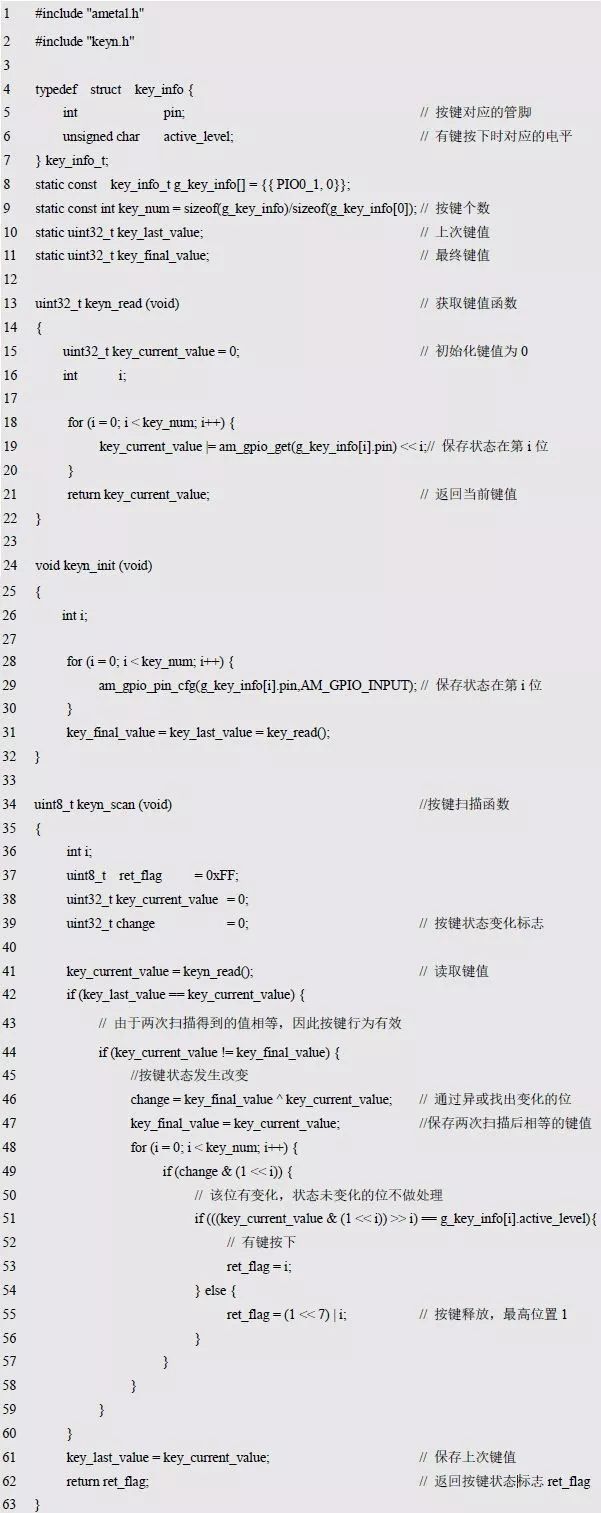
Based on the logic of a single button, the program keyn.c supports multiple independent buttons. See Listing 5.45 for details.
Listing 5.45 Scanner That Supports Multiple Independent Buttons (keyn.c)
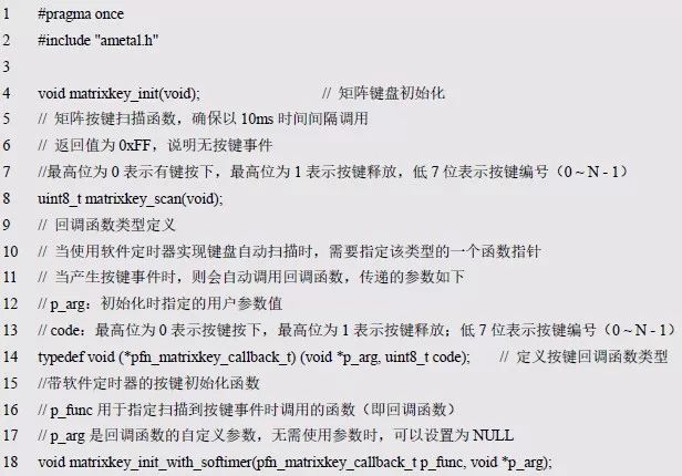
The function declarations and type definitions are stored in keyn.h, as shown in Listing 5.46.
Listing 5.46 keyn.h File Contents

The programming approach for multiple buttons is similar to that of a single button, with most of the code remaining unchanged. The difference lies in the use of multiple bit operations to track changes in each button. The return value of the scan function includes both the state (press or release) and the specific button that changed.
>>> 5.3.3 Matrix Keyboard
Although matrix connections improve I/O efficiency, they require more complex methods to distinguish and detect button actions. This connection is commonly used in computers. Using the 2x2 matrix keyboard shown in Figure 4.15 as an example, we'll explain the programming method for scanning row-by-row.
Listing 5.50 matrixkey.h File Contents
Listing 5.51 matrixkey.c File Contents
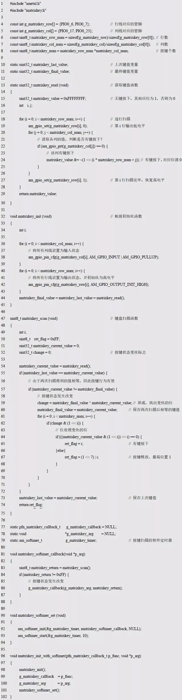
To reuse the previous independent button code, the scanned button states correspond to bits of the key value. When a key is pressed, its corresponding bit is 0; when released, it's 1. The row lines must be configured as outputs, and the column lines as inputs during initialization. The main difference between a matrix keyboard and an independent key is the way the key value is obtained.
5.4 PWM Interface
Alternating Current (AC) is a current whose magnitude and direction vary periodically over time. The basic waveform of AC is a sine wave, while others are non-sinusoidal. Pulse waves, sawtooth waves, etc., are common in devices like computers and radars.
PWM (Pulse Width Modulation) is a technique that modulates the width of pulses according to the signal level. The period of the pulse-width-modulated wave is fixed, and the duty ratio (high level / period) determines the coded value, ranging from 0 to 100%. PWM can be used to digitally encode analog signals or control motor speed and LED brightness by adjusting energy output over the entire cycle.
PWM signals are generated using a counter and comparator. A threshold is set in the comparator, and the counter increments at a certain frequency. When the counter value is less than the threshold, a high level is output; when greater, a low level is output. Upon overflow, the counter resets to 0, creating a periodic PWM waveform.
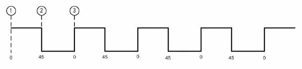
Figure 5.3 PWM Waveform Diagram
>>> 5.4.1 Initialization
Before using the PWM interface, the PWM must be initialized to obtain a standard PWM instance handle. In the LPC82x, the SCT (State Configurable Timer) provides a PWM output function. It acts as a state-programmable timer that can be used for normal timing, input capture, and PWM output.

The returned PWM instance handle is of type am_pwm_handle_t and is used as an argument in the PWM general interface. If the handle is NULL, the initialization failed and cannot be used.
>>> 5.4.2 PWM Interface Function
AMetal provides three standard PWM output interface functions. These include configuring the channel, enabling, and disabling the output.
Table 5.9 PWM Standard Interface Functions
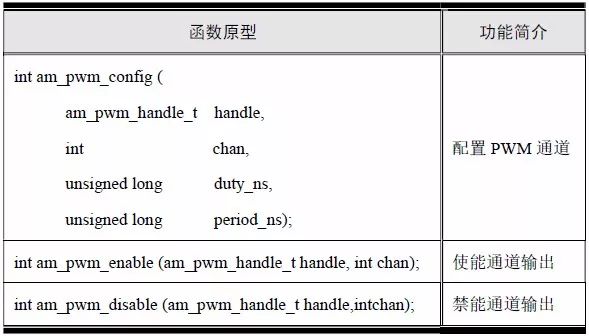
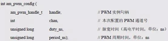
1. Configuring the PWM Channel
Configures the cycle and high time of a PWM channel. The function prototype is as shown in Listing 5.54.
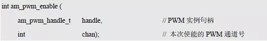
2. Enable Channel Output
Enables the channel output so that the corresponding waveform starts. The function prototype is shown in Listing 5.55.
3. Disable Channel Output
Disables the channel output and stops the waveform. The function prototype is shown in Listing 5.56.

>>> 5.4.3 Buzzer Interface Function
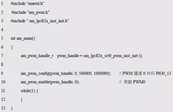
In a buzzer sounding program, even a 500us delay is resource-intensive for the MCU. Instead, the PWM output function can directly drive the buzzer. Assuming a 1ms period with a 50% duty cycle, the sample program is shown in Listing 5.57.
Listing 5.57 Buzzer Sounding Sample Program
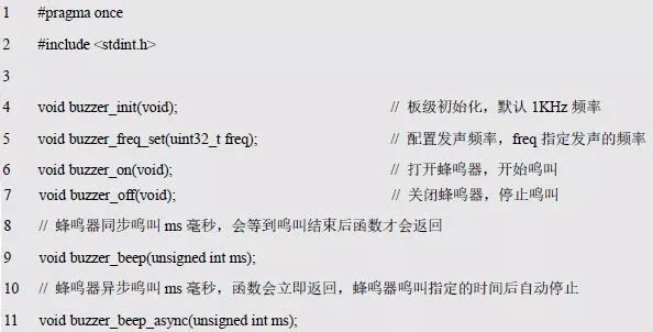
A general-purpose buzzer interface is written based on the PWM interface function, with declarations and implementations in buzzer.h and buzzer.c. This allows direct calls to the buzzer-related interface, as shown in Listing 5.58.
Listing 5.58 Buzzer Universal Interface
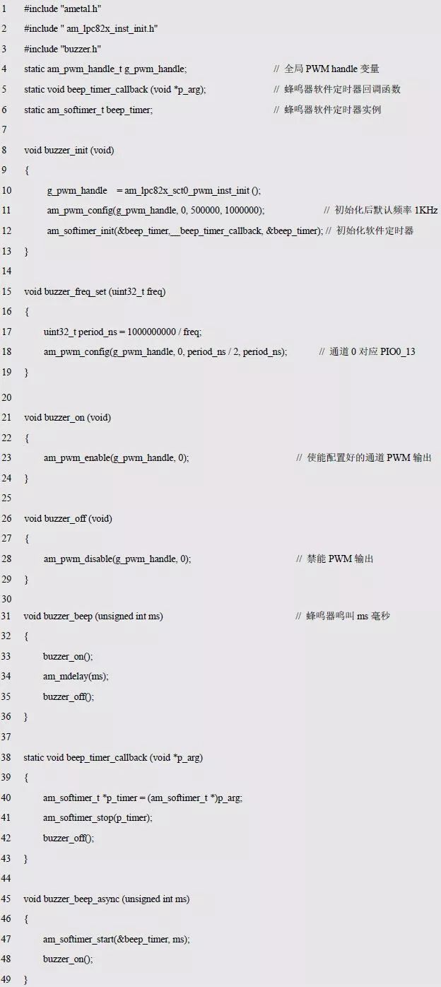
The implementation of the interface is placed in buzzer.c, as shown in Listing 5.59.
Listing 5.59 Buzzer Universal Interface Implementation
The DMX console is the central controller for controlling all stage lights and special effects equipment. Almost all equipment needs to be connected to it, and users use it to issue control commands to all equipment. It can be controlled in real time, or the device can be programmed to display specific effects at a fixed time. Even with the stage equipment, the DMX console is also essential, just like there are more soldiers, the commander still needs to give orders to them. There are also many different types controllers to work for different quantity Stage Lights.

DMX Controller, DMX Consule
Guangzhou Cheng Wen Photoelectric Technology Co., Ltd. , https://www.cwdisplay.com