
The ChipScope Pro Analyzer tool connects directly to the ICON, ILA, IBA, VIO, and IBERT cores, allowing users to create or modify trigger conditions in real time.
Note: Although the ChipScope Pro analysis tool recognizes the ATC2 core in the design, it is necessary to connect the JTAG interface to the Agilent logic analyzer to establish communication between the ATC2 core and the Agilent logic analyzer.
The analysis tool has two parts: the analysis tool server and the client.
(1) The server is a command line service program that can be connected to the JTAG port of the target device through the JTAG download cable. If the user wants to debug the local target system through the JTAG download line, there is no need to manually open the analysis tool server. Only when the user needs to connect to the remote client, the analysis tool server needs to be manually opened.
(2) The Analysis Tool Client is a graphical user interface (GUI) that connects to the JTAG chain of the target system and communicates with the ChipScope core in the target device. The client and server of the analysis tool can run on one machine (local host mode) or on different machines (remote mode). The remote mode is useful in the following situations.
Debug a remote system.
Share a system resource with other colleagues.
Demonstrate questions or features to remote customers.
In most cases, the user analyzes the design through the Analysis Tool client, which details the client interface and functionality. The client interface is shown in Figure 9-38.
![[Chipscope Pro Analyzer tool] client interface](http://i.bosscdn.com/blog/0H/T3/J0/5_0.png)
Figure 9-38 [Chipscope Pro Analyzer tool] client interface
The analysis tool client consists of a menu bar, a common toolbar, a project browser, a signal browser, a main window, and an information display window.
(1) Menu bar.
[File] File menu: Contains operations related to the project, such as [New Project] new project, [Open Project] open project, [Save Project] save project, [Save Project As] project save, [Page Setup] page setup, [Print] Print, [Import] import, [Export] export, and [Exit] exit commands. Among the more important import and export functions, the [Import] import is used to obtain the signal list from the design file, and the [Export] export is used to extract the captured data for subsequent observation and processing.
[View] view menu: Contains two commands for displaying the [Project Tree] project browser and displaying the [Messages] information display window.
[JTAG Chain] Boundary Scan Link Menu: Contains commands related to downloading cables, such as [Serve Host SetTIng] host service settings, [JTAG Chain Setup] JTAG chain establishment, [Xilinx parallel Cable] connection to Xilinx parallel download line, [ Xilinx parallel USB Cable] Connect the Xilinx parallel USB download cable, [Close Cable] to close the cable, [Get Cable InformaTIon] to obtain cable information and [Auto Core Status Poll] to open the automatic core status query.
[Device] Device menu: Contains [JTAG Device Chain Setup] boundary scan chain settings, [Configure] configuration device, [Show IDCODE] display device identification code and [Show USERCODE] display user code and other commands.
[Windows] window menu: contains the [New Unit Window] new window unit, [Close] off, [Auto Layout] automatic rearrangement and other related commands.
[Help] Help menu: Contains version information and all nuclear information.
(2) Project Browser: After the JTAG boundary scan chain is properly initialized, the project browser will list all the recognized devices on the scan chain, display the number of cores, and create a folder for each core, which contains the trigger conditions. Set and analyze the waveform file of the signal. After the configuration download is complete, the project browser will also be updated.
(3) Signal Browser: The Signal Browser is used to add and delete signals in the view. When a ChipScope core is selected in the Project Browser, signals related to this core will be displayed in the Signal Browser. Rename or combine signals into a form of bus.
Name the signal and bus, double-click or right-click and select [Rename] to rename the signal and bus name.
Add/remove signals from the window. Use [Clear All] → [Waveform] or [Clear All] → [LisTIng] command to delete the signal. Use the [Add ALL To View] command to add a signal.
Merge/add signals to the bus. For the ILA core and the IBA core, only the data signals can be combined with the bus, and for the VIO core, various types of signals can be grouped. Click the signal to be grouped and select [Add To Bus] → [New Bus] to reorder the bus signals. Use the [Reverse Bus Order] command to change the bus sequence from LSB to MSB to MSB to LSB.
(4) Main window: The main window is mainly used to display windows such as [Trigger Setup], [Wavaform], [LisTIng], and [Bus Plot].
(5) Information display window: The information display window will list all the status information of the analyzer for the user to view.
When using Analyzer to observe the signal waveform, you first need to download the configuration file generated by the design and ChipScope Pro core to the FPGA chip. The data is then captured by setting different trigger conditions, stored in the BRAM of the chip, and read back to the PC through the JTAG chain to observe the waveform.
Open Analyzer, click on the common toolbar to initialize the boundary scan chain. After the scan is successfully completed, the project browser will list the devices on the JTAG chain, as shown in Figure 9-39. Analyzer automatically recognizes all Xilinx CPLDs, FPGAs, PROMs, and System ACE chips on the boundary scan chain. Figure 9-39 shows the JTAG chain scan results for the ML505 target board.
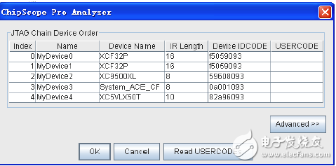
Figure 9-39 Analyzer boundary scan results
BNC Female Bulkhead Waterproof Connector,Bulkhead BNC Connector,BNC Bulkhead Connector Female,BNC Compression Connector
Xi'an KNT Scien-tech Co., Ltd , https://www.honorconnector.com