
A clear trend in many end markets and applications is the replacement of AC or mechanical pumps with high efficiency brushless DC motors (BLDC). For precise motor control and efficient commutation, high-resolution current and rotational position information is critical. Although a sensorless solution can be used to detect back EMF current, motor starting performance can be a problem.
An alternative is to use angle sensors based on anisotropic magnetoresistance (AMR) technology, which are both inexpensive and accurate. With ARM sensors, not only high angle accuracy, but also a sensing element and electronic circuitry can be integrated in the same package. This results in a very small sensor subsystem and the ability to position the sensor within the motor assembly.
ADI has partnered with Sensitec GMBH, the leader in MR technology, to offer the ADA4571, which combines high-precision AMR sensors and high-performance instrumentation amplifiers in a single package.

The ADA4571's production test at a wide operating temperature range of 40°C to +150°C yields a maximum angular error of 0.5° with built-in diagnostics, large output levels, EMC protection, and low offset offset. It is an ideal sensor for high performance BLDC motor control with speeds in excess of 25,000 RPM.
AMR technology
The material resistivity of a sensor based on the AMR concept depends on the direction of magnetization relative to the direction of the current. The sensor is typically deposited as a thin film permalloy (magnetic iron-nickel alloy). The AMR sensor operates in saturation, so the external magnetic field determines the change in resistance. When the external magnetic field and the current direction are parallel, the resistance is the largest, and the applied magnetic field has the smallest resistance when perpendicular to the plane of the current-carrying magnetic alloy. A simplified diagram of how the AMR sensor works is shown in Figure 1.

Figure 1. How AMR works
When two independent Wheatstone bridge configurations are arranged at 45° to each other, an angle sensor can be implemented whose sine and cosine outputs depend on the direction of the external magnetic field. This configuration provides a sensor with an absolute measurement range of 180°.

Figure 2. ADA4571 error (gray) and output waveform (orange/blue) for 360° mechanical rotation
Figure 2 shows the typical high output level and angular error of the ADA4571 when a rotating magnetic field is applied in a 360° mechanical rotation. Typical errors are less than 0.1° after offset correction and arctangent calculations in the microcontroller.
Sensor installation
For most BLDC control systems, there are many options for configuring and installing the sensor based on the available space and the ease of motor shaft mounting. Figure 3 shows two configuration examples of the ADA4571.
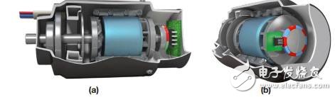
Figure 3. BLDC system and ADA4571 (a) shaft end system (b) shaft side system
A typical shaft end configuration includes a diameter magnetized disc magnet mounted on a rotating shaft that is mounted inside the motor assembly as shown in Figure 3(a). The magnet provides a magnetic field that passes through the plane of the sensor.
In this configuration, the rotor angle can be read directly without touching the mechanical and electrical components. Since the AMR technology does not rely on the strength of the magnetic field, it can withstand the change in the air gap. Independent of the magnetic field strength can also increase the mechanical tolerance and simplify the selection of the magnet material.
The compact shaft end configuration means that the sensor can be mounted directly on a printed circuit board (PCB) that is very close to the electronic control unit (microcontroller, MOSFET), minimizing signal routing and reducing the distance from harsh motor environments.
Another possible configuration is the axle side system shown in Figure 3(b). The shaft side configuration can be used for applications where the shaft to be tested cannot be mounted with magnets at the ends. In this configuration, the excitation is provided by the pole ring, and the sensor and pole ring can be mounted anywhere on the shaft. Typical applications include electric power steering pumps or BLDC motors that cannot be used with shaft ends due to space constraints.
Because the ADA4571 provides low latency and accurate position feedback, the current in each phase of the motor can be precisely controlled to allow the motor to respond smoothly to dynamic loads or to maintain constant speed under varying conditions. The end result is better control, maximum torque, higher start/stop efficiency, and better health.
Sensor setup and calibration
For higher accuracy, various calibration procedures can be performed at the end of the user's production line. A one-time offset calibration can be performed to eliminate the initial offset of the sine and cosine signals. Figure 4 shows typical performance after performing a one-time offset calibration at room temperature.
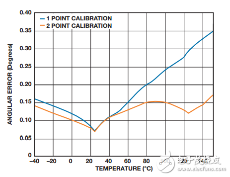
Figure 4. Typical angular error versus temperature for single and double point calibration
Due to the offset drift of the sensor, the angular accuracy may decrease with increasing temperature, such as single point calibration at 150 °C, while double point temperature calibration improves performance. In this case, the information of the offset and on-chip temperature sensors can be interpolated and the offset with temperature can be compensated for.
The BLDC system in a free-running application can take advantage of continuous offset correction techniques by calculating the mean of the sensor output over a specified time period. Dynamic offset compensation in the microcontroller enables very high accuracy over the entire temperature range and operating life.
Unlike other sensor technologies (Hall/GMR/TMR), the ADA4571 does not require additional calibration steps such as amplitude correction or orthogonality correction. The amplitude mismatch guaranteed by production testing ensures less than 1%, while advanced sensor design ensures orthogonality. The sensor also ignores hysteresis, resulting in highly reliable and accurate position information.
For applications that do not require high accuracy, low performance, and cost sensitivity, the ADA4571 can be used without line termination offset correction. In this case, the ADA4571 ensures an angular error of less than 5°. This is useful for some uncalibrated applications because the host controller knows the position of the axis and therefore optimizes the startup condition.
in conclusion
Magnetic position sensors provide small, stable and easy to assemble position detection solutions for industrial and automotive BLDC motor control system designers. ADI's new ADA4571 offers high-speed, high-precision, production-tested full-angle accuracy, integrated diagnostics, and low-power operation, significantly better than previous generations of magnetic position sensors.
Homemade library ground wave TV double ring indoor antenna: The received ground decimeter wave frequencies are currently in the 500-800 MHZ frequency range. If there is a good field strength in the urban area, low frequency and high frequency should be taken into account. This is the best resonance; The frequency center is around 700MHz, which is converted according to the radio propagation speed and frequency. If the center frequency wavelength is about 42cm, then the diameter of the ring antenna should be 13cm, that is, the diameter should be a quarter of the center frequency wavelength of about 42cm. If we think of a 42cm conductor as a ring with a central frequency and wavelength of 42cm, then its diameter should be close to 13cm. If we make a good antenna, we can get twice the result of receiving ground waves with half the effort!
Indoor Antenna for TV ,Indoor Antenna Walmart,Indoor Antenna Best,Indoor Antenna for Router ,Indoor Antenna for Booster
Yetnorson Antenna Co., Ltd. , https://www.yetnorson.com