
To generate sparks, the devices you need include power supplies, batteries, transformers (ie, ignition coils), and switches that control the primary current of the transformer. The electronics textbook tells us that V=Ldi/dt. Therefore, if the current in the primary winding of the coil changes instantaneously (i.e., the di/dt value is large), a high voltage will be generated on the primary winding. If the turns ratio of the ignition coil is N, the primary side voltage can be amplified according to the winding turns ratio. The result is a voltage of 10kV to 20kV across the secondary, spanning the spark plug gap. Once the voltage exceeds the dielectric constant of the air surrounding the gap, the gap will be broken down to form a spark. The spark ignites the mixture of fuel and air to produce the energy needed to operate the engine (Figure 1).
In addition to diesel engines, all internal combustion engines have a basic circuit (automobile ignition system). Switching elements for ignition coil charging have undergone great evolution: from a single mechanical switch, multiple breaker contacts in a distributor, to a high-voltage Darlington bipolar installed in a distributor or in a separate electronic control module The transistor is connected to an insulated gate bipolar transistor (IGBT) mounted directly on the ignition coil of the spark plug, and finally the smart IGBT directly mounted in the ignition coil of the spark plug.
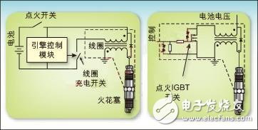
Figure 1: Schematic diagram of the car ignition system
Advantages of IGBT
Many years ago, IGBTs have become switches in ignition applications. Figure 2 shows a cross-sectional view of the IGBT. Compared with other technologies, IGBT has the following important advantages:
1. The saturation pressure at high current is reduced;
2. It is easy to construct a circuit that can handle high voltage coils (400~600V);
3. Simplified MOS drive capability;
4. Can withstand high energy consumption (within SCIS rated range) when the coil is working abnormally.
The schematic diagram of the ignition IGBT shown in Figure 2 includes several additional important elements. The collector-to-gate avalanche diode stack establishes a "on" voltage. When the collector is forced to rise to this voltage by a flyback or spike from the coil, the IGBT will conduct, and the IGBT will consume its active area. The remaining energy accumulated in the coil (rather than using it to create a spark). With this avalanche "clamp" circuit, the IGBT limits the clamping voltage to a much lower breakdown voltage than the N epitaxial doped/P-based semiconductor to ensure its safety. run. This significantly increases the ability of the ignition IGBT to withstand the energy of the self-clamping inductive switch (SCIS). This capacity is a rated indicator, that is, the energy absorbed by the IGBT each time the energy in the ignition coil is released as a spark. By limiting the voltage on the primary coil, the ignition coil itself is also over-voltage protected.
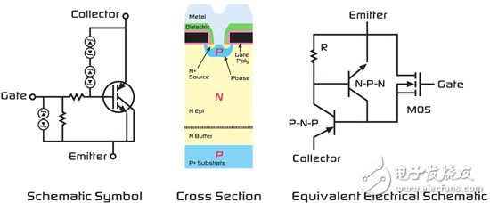
Figure 2: IGBT profile
The latest generation of IGBTs has been able to significantly reduce the die area in IGBTs while still maintaining excellent SCIS capability. This advancement is spawning multi-die smart IGBT products. This type of smart product combines high-performance BCD IC technology with high-performance power discrete component IGBTs. The demand for intelligent IGBT coil drive circuits is due to the fact that the development direction of the power switch is changed from an external engine control module to a component located directly in the ignition coil on the spark plug in the engine. When the ignition coil is located on a spark plug, this structure is referred to as a "coil on plug"; when the coil drive circuit is included in the coil, this structure is referred to as a "switch on coil."
The "switch on coil" structure offers significant advantages in terms of system performance, reliability and cost. Some of its advantages are as follows:
1. No high voltage spark plug wire is required;
2. No heat is generated in the engine control module;
3. Save space in the engine control module;
4. Improves engine control by monitoring actual spark generation.
The last performance advantage has spurred demand for smart IGBTs. As a result, automotive ignition switch functions are evolving into smart devices that monitor spark conditions, take current limiting measures to protect the coil, and pass the engine's ignition status to the engine control system.
The ideal smart IGBT function in the "switch on coil" application
1. Signal interface of the engine control module
There are many problems with the "on-coil switch" smart IGBT driven by the engine control module. The electrical environment noise under the hood is very disturbing. The signal interface of the engine control module not only needs to cope with these noises, but also solves the potential problem of several meters of connection between the engine control module and the coil position. Electrical noise may come from EMI radiated signal noise or magnetic induction noise caused by large currents in adjacent lines.
In addition to the noise problem described above, the actual ground reference point of the engine control module has a voltage differential of several volts from the ground point at which the coil or engine is located. Therefore, the defined interface between the engine control module and the intelligent ignition coil drive circuit must be able to cope with these problems.
2. Protect the ignition coil
The input signal in Figure 3 commands the IGBT to begin charging the ignition coil. Under normal conditions, when the coil stops charging and releases sparks, the current will reach 7~10A. However, when the engine is at a low speed, especially during an emergency deceleration or engine control time, if the input is not cut, the IGBT will cause the coil charging current to exceed the rated value, which may cause damage to the coil winding.
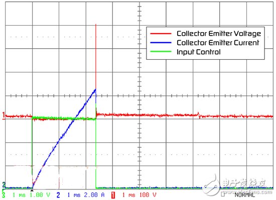
Figure 3: Typical ignition waveform
Smart IGBTs have been designed with several circuits to prevent ignition coils from being damaged in this situation.
The first is a current limiting circuit that directly measures the IGBT collector current with a sense resistor or with a current sense IGBT. Figure 4 shows these two circuits.
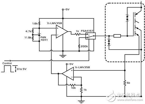
Figure 4: Current limiting circuit
Solar Stake Lights,Outdoor Stake Lights,Solar Garden Stake Lights,Outdoor Solar Stake Lights
Jiangmen Biaosheng Solar Energy Technology Co., Ltd. , https://www.bsprosolar.com