Overview Flyback LED drivers are more versatile because this structure can be used for input voltages that are higher or lower than the required output voltage. In addition, when the flyback circuit works in discontinuous inductor current mode, it can keep the LED current constant without additional control loops. The circuit described in this application note is based on the highly integrated MAX16802 PWM LED driver IC. Application LED track lighting general LED lighting equipment Features 10.8V to 24V input voltage range powers a single 3.3V LED, providing 350mA (typical) current (other LED configuration structures, please follow the design steps to design) 29V (typical) anode to ground maximum open circuit voltage 262kHz switching frequency Weekly cycle on / off control input allows the use of low-frequency PWM signals to adjust the brightness. The circuit can be adjusted to adapt to various forms of series and parallel LED configuration. Typical application circuit
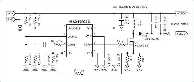
Note: When + VLED and -VLED are not connected to the LED, do not power the circuit.
Component list| DesignaTIon | Qty. | DescripTIon |
| C1 | 1 | 1nF ± 10%, 50V X7R ceramic capacitor (0603) TDK C1608X7R1H102K |
| C2 | 1 | 220pF ± 10%, 50V X7R ceramic capacitor (0603) TDK C1608X7R1H221K |
| C3, C4, C7 | 3 | 0.1µF ± 10%, 50V X7R ceramic capacitor (0603) TDK C1608X7R1H104 |
| C5 | 1 | 10µF ± 10%, 25V X7R ceramic capacitor (1206) TDK |
| C6 | 1 | 10µF ± 10%, 16V X7R ceramic capacitor (1206) TDK C3216X7R1C475K |
| D1 | 1 | 40V, 1A Schottky diode (SMA) CMSH1-40M Central Semiconductor |
| L1 | 1 | 10µH inductor Coilcraft DO3308P-103 |
| Q1 | 1 | 40V, 0.045W MOSFET Vishay Si2328DS |
| R1, R3 | 2 | 499k |
| R2 | 1 | 22.1k |
| R4 | 1 | 73.2k |
| R5 | 1 | 100k |
| R6 | 1 | 150 |
| R7 | 1 | 100 |
| R8 | 1 | 10 |
| R9, R10 | 2 | 1 |
| R11 | 1 | 1 |
| U1 | 1 | PWM IC Maxim: MAX16802AEUA (8-pin µMAX®) |
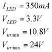
The circuit topology is open loop, and the non-isolated flyback LED driver is very versatile and easy to use. It has a series of advantages and is very popular. These advantages include: Adjustable LED current without external control loop Discontinuous inductor current transmission Reduce switch conduction loss with low EMI radiation Simple circuit design process LED voltage can be higher or lower than input voltage Wide input voltage range The biggest advantage of being able to easily access the PWM brightness adjustment signal is simplicity, at the cost of the following disadvantages: LED current is affected by component tolerances, for example, the inductance and current-sensing comparator transmission delay discontinuous inductor current operating mode makes this topology The most important parameter in the design step of the structure that is more suitable for low-power applications is the LED current. The working current of high-brightness LED is generally several hundred mA. In order to extend the working life of the LED, the current must be kept constant; the power supply is essentially a current driver. Can be achieved through several solutions, a simple and low-cost solution is: the use of a dedicated current mode PWM controller IC, such as MAX16802. The advantages of this device are: High integration-few external components are required up to 262kHz. The switching frequency is very small. The small 8-pin µMAX package has a small current-sense threshold, which reduces the loss. The very accurate oscillation frequency helps reduce the LED current. The on-chip voltage feedback amplifier can be used to limit the output open circuit voltage. The given LED parameters are:
Step 1: Calculate the approximate value of the best duty cycle at the minimum input voltage:

Where Rb is the rectifier resistance, the same as R11 in the application circuit, set to 1 in this application . VD is the forward voltage drop of the rectifier diode D1.
Substituting the known value into the above formula gives:

Step 2: Calculate the approximate value of the peak inductor current:

Where Kf is the critical "error coefficient", which is set here to 1.1.
Substitute the known value into the above formula to get:

Step 3: Calculate the approximate value of the required inductance, and select the standard inductance less than and closest to the calculated value:

Among them L is L1 in the application circuit; f is the switching frequency, equal to 262kHz.
Substitute the known value into the above formula to get:

Below this value, the closest standard value is 10µH.
Step 4: Power delivered to the output through the flyback process:

The power loss of the output circuit is equal to:

According to the principle of conservation of energy, the above two equations should be equal to obtain a more accurate peak inductor current:

Where L is the actual selected standard inductance value.
Substituting the known value into the above formula gives:

Step 5: Calculate the current detection resistance, which is obtained by connecting R9 and R10 in parallel; calculate the voltage detection resistance (if necessary), which consists of R6 and R7.
The current-limit threshold of the MAX16802 is 291mV. Therefore, select R9, R10, R6 and R7 to meet the peak inductor current calculated in step 4.
After this step is completed, you can get the value of each component in the application circuit, the circuit can provide 12V, 350mA output. Because of the parasitic effect, the resistance value (R7) needs to be adjusted appropriately to obtain the desired current.
Step 6: R1 and R2 are optional. They are used to adjust + VLED to 29V. This is very useful when there is an accidental open circuit at the output. Without the voltage division of the above components, the output voltage may rise, causing damage to the device.
Components C1 and R5 are also optional and used to stabilize the voltage feedback loop. For current applications, these components may not be used.
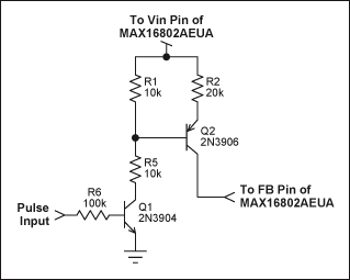
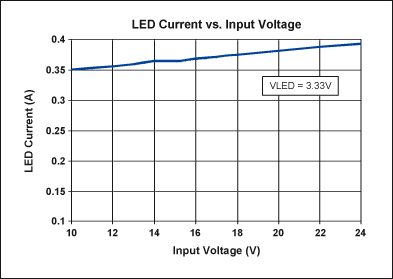
Low-frequency PWM brightness adjustment The best way to control the brightness of the LED light source is to modulate the LED current through a low-frequency PWM pulse. Using this method, the LED current triggers a pulse based on the change in duty cycle, while keeping the current amplitude constant. In this way, the wavelength of the light wave emitted by the device remains unchanged throughout the adjustment range.Use the following circuit to achieve PWM brightness adjustment.
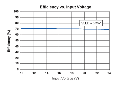
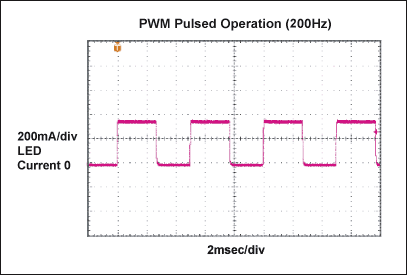

Our Led Flood Light is energy saving,led based,wash fixture,incorporating high power LEDs. LED color is available in RGB color changing,or single color. Our products are supplied with a low current and thereby generate long-lasting light.Other manufacturers supply LEDs with a maximum current,to generate the required brightness with less LED chips,however,has negative effects on the longevity of every single LED.Our products are manufactured with more LED chips.And the housing is composed of die-casting aluminum fixture,good at resistance against oxidation,making the housing durable,exquisite and graceful,waterproof well,. Constant current driving ensure the stable and reliable performance. Adjustable beam angle to fulfill your satisfactory effect. Led flood light is widely applied in building facade,stadium,flyover,monument,park and parterre,to render the atmosphere,increasing the visual effect.
Led Flood Light
Led Flood Light,Outdoor Flood Light,Exterior Flood Lights,Led Flood Light Fixtures
Guangdong guangzhidian lighting Co., Ltd. , https://www.gzdlighting.com
