
**I. Overview:**
**1. Introduction to LED**
A Light-Emitting Diode (LED) is a semiconductor device that emits light when an electric current passes through it. LEDs are commonly used in various electronic applications due to their efficiency, durability, and low power consumption. They are available in different colors such as red, green, and yellow. The reverse breakdown voltage of an LED is typically around 5V, which means it should not be exposed to voltages higher than this in reverse bias.
The forward voltage-current characteristic of an LED is very steep, meaning even small changes in voltage can cause large changes in current. To prevent excessive current from damaging the LED, a current-limiting resistor must be connected in series with it. The value of this resistor can be calculated using the formula:
**R = (E - UF) / IF**
Where:
- **E** is the supply voltage,
- **UF** is the forward voltage drop of the LED,
- **IF** is the desired operating current of the LED.
LEDs are widely used in electronic circuits for indicators, such as power status, signal levels, or activity lights in devices like home appliances, meters, and more.
**2. STM32 GPIO Introduction**
The STM32F4 series microcontroller features general-purpose I/O (GPIO) ports that can be configured for multiple functions. Each GPIO port includes several registers, such as MODER (mode register), OTYPER (output type register), OSPEEDR (output speed register), PUPDR (pull-up/pull-down register), IDR (input data register), ODR (output data register), BSRR (bit set/reset register), LCKR (lock register), and AFRH/AFRL (alternate function registers).
GPIO pins can be configured into eight different modes:
- **Floating Input**: The pin is in a high-impedance state, often used for communication interfaces.
- **Pull-Up Input**: The pin has an internal pull-up resistor, ensuring a default high level if no signal is applied.
- **Analog Input**: Used for ADC input, where the pin is disconnected from internal resistors and triggers.
- **Open-Drain Output**: The output can only drive low; a pull-up resistor is needed to achieve a high level.
- **Push-Pull Output**: The pin can drive both high and low levels directly.
- **Open-Drain Alternate Function**: Similar to open-drain output but controlled by an internal peripheral.
- **Push-Pull Alternate Function**: Similar to push-pull output but controlled by an internal peripheral.
These configurations allow the STM32 to interface with a wide range of external devices and peripherals.
**II. Hardware Circuit:**
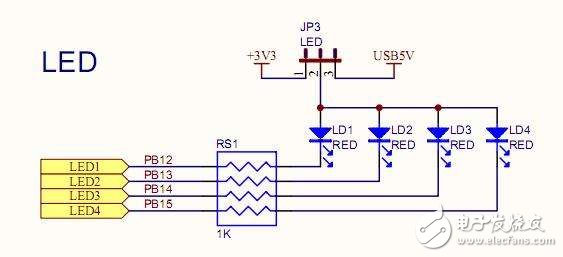
On the iCore3 dual-core development board, three separate RGB LEDs are connected to the STM32F407 microcontroller. Each LED is connected via a 1kΩ current-limiting resistor. Specifically, the red LED is connected to PI5, the green LED to PI6, and the blue LED to PI7. This setup allows the microcontroller to control each color independently.
**III. Experimental Principle:**
In this experiment, the three-color LED is controlled using three GPIO pins of the STM32. The GPIO pins are configured in push-pull output mode, which allows them to drive both high and low levels. When a GPIO pin outputs a high level, the corresponding LED turns off; when it outputs a low level, the LED turns on. By cycling through the different colors, the LED can be made to flash in sequence.
**IV. Source Code:**
**1. Main Function**
```c
/*
* Name : main
* Description : Main function for the LED blinking program
* Author : ysloveivy
* History
* --------------------
* Rev : 0.00
* Date : 11/21/2015
* create.
* --------------------
*/
int main(void) {
int i;
Led.initialize();
// Three-color LEDs blink alternately
while(1){
LED_RED_ON;
LED_GREEN_OFF;
LED_BLUE_OFF;
for(i = 0; i < 10000000; i++);
LED_RED_OFF;
LED_GREEN_ON;
LED_BLUE_OFF;
for(i = 0; i < 10000000; i++);
LED_RED_OFF;
LED_GREEN_OFF;
LED_BLUE_ON;
for(i = 0; i < 10000000; i++);
}
}
```
**2. GPIO Initialization**
```c
/*
* Name : initialize
* Description : Initialize the GPIO for the LED
* Author : ysloveivy
* History
* --------------------
* Rev : 0.00
* Date : 11/21/2015
* create.
* --------------------
*/
static int initialize(void) {
GPIO_InitTypeDef GPIO_uInitStructure;
// Enable clock for GPIOI
RCC_AHB1PeriphClockCmd(RCC_AHB1Periph_GPIOI, ENABLE);
// Configure the IO pins for the RGB LED
GPIO_uInitStructure.GPIO_Pin = GPIO_Pin_5 | GPIO_Pin_6 | GPIO_Pin_7;
GPIO_uInitStructure.GPIO_Mode = GPIO_Mode_OUT;
GPIO_uInitStructure.GPIO_OType = GPIO_OType_PP; // Push-pull output
GPIO_uInitStructure.GPIO_PuPd = GPIO_PuPd_UP; // Pull-up
GPIO_uInitStructure.GPIO_Speed = GPIO_Speed_100MHz;
GPIO_Init(GPIOI, &GPIO_uInitStructure);
// Set the initial state to high (LEDs off)
GPIO_SetBits(GPIOI, GPIO_Pin_5 | GPIO_Pin_6 | GPIO_Pin_7);
return 0;
}
void GPIO_Init(GPIO_TypeDef* GPIOx, GPIO_InitTypeDef* GPIO_InitStruct) {
// Function implementation
}
```
**Structure Definition:**
```c
typedef struct {
uint32_t GPIO_Pin; // Select the pin
GPIOMode_TypeDef GPIO_Mode; // Set the mode
GPIOSpeed_TypeDef GPIO_Speed; // Set the speed
GPIOOType_TypeDef GPIO_OType; // Set the output type
GPIOPuPd_TypeDef GPIO_PuPd; // Set pull-up/pull-down
} GPIO_InitTypeDef;
```
**V. Experimental Phenomenon:**
The three-color LED connected to the ARM section of the iCore3 dual-core board (labeled as ARM·LED on the PCB) flashes in sequence, with red, green, and blue LEDs turning on one after another. This demonstrates the ability of the STM32 to control multiple outputs and create visual effects through simple programming.
Fiber Pen Nib,Passive Capacitive Stylus Pen,Rubber Tip Stylus Pen,Microsoft Stylus Pen
Shenzhen Ruidian Technology CO., Ltd , https://www.wisonen.com