
Adjacent channel power ratio (ACPR) of the cable upstream amplifier MAX3510 / MAX3514 / MAX3516
Abstract: The performance specifications of the cable upstream drive amplifier MAX3510 / MAX3514 / MAX3516 are given in the article. ACPR and gain data are given in the form of graphs and tables. The unit complies with the DOCSIS 2.0 standard. The data is tested in the 5MHz to 65MHz frequency band.
More information
Measure the adjacent channel power ratio (ACPR) of the MAX3510 / MAX3514 / MAX3516. The test conditions are 5.0V power supply voltage, input signal + 34dBmV. The test results in graphical representation are given. The data conforms to the DOCSIS 2.0 standard.
ACPR is an important parameter of cable amplifiers, because the transmitted carrier may appear on adjacent channels, and this channel will be occupied by carriers with the same or different modulation rates. ACPR is defined as the carrier power ratio of the main channel and the phase-zero channel. According to the DOCSIS standard, a test bandwidth of 160 kHz is used, and the channel spacing is 200 kHz.
The MAX3510 / MAX3514 / MAX3516 are a series of controllable gain upstream amplifiers designed for CATV upstream applications. They operate in the 5MHz to 65MHz band and can drive QPSK signals (MAX3516) up to + 64dBmV. Because both input and output are differential, a non-balancer transformer is required outside the output port. The variable gain feature provides a dynamic range above 56dB (MAX3514 / MAX3516), controlled by the SPI 3-wire interface. The gain control is in 0.5dB (MAX3514 / MAX3516) or 1dB (MAX3510) steps.
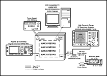
Click on the big picture 1. Test equipment 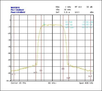
figure 2.
Table 1. Correspondence between MAX3510 ACPR and output power and frequency
| Input (dBm) | GCW | Output (dBm) | Output (dBmV) | ACPR (dBc) | |
| 5MHz | -13 | 49 | 4.41 | 51.41 | -66 |
| -13 | 52 | 7.16 | 54.16 | -66 | |
| -13 | 55 | 9.92 | 56.92 | -64.5 | |
| -13 | 59 | 13.59 | 60.59 | -61.2 | |
| -13 | 61 | 15.5 | 62.5 | -51.8 | |
| -13 | 63 | 17.03 | 64.03 | -42 | |
| 20MHz | -13 | 49 | 4.03 | 51.03 | -66 |
| -13 | 52 | 6.82 | 53.82 | -65.3 | |
| -13 | 55 | 9.59 | 56.59 | -64 | |
| -13 | 59 | 13.29 | 60.29 | -60.3 | |
| -13 | 61 | 15.19 | 62.19 | -51.7 | |
| -13 | 63 | 16.72 | 63.72 | -42.2 | |
| 42MHz | -13 | 50 | 4.30 | 51.30 | -66 |
| -13 | 53 | 7.29 | 54.29 | -63.6 | |
| -13 | 56 | 10.06 | 57.06 | -61.5 | |
| -13 | 59 | 12.81 | 59.81 | -58.6 | |
| -13 | 61 | 14.76 | 61.76 | -50.1 | |
| -13 | 63 | 16.29 | 63.29 | -41.8 | |
| 65MHz | -13 | 50 | 3.95 | 50.95 | -65.5 |
| -13 | 53 | 6.73 | 53.73 | -62.6 | |
| -13 | 56 | 9.5 | 56.5 | -59.6 | |
| -13 | 59 | 12.26 | 59.26 | -56.9 | |
| -13 | 61 | 14.24 | 61.24 | -50.1 | |
| -13 | 63 | 15.76 | 62.76 | -40.5 |
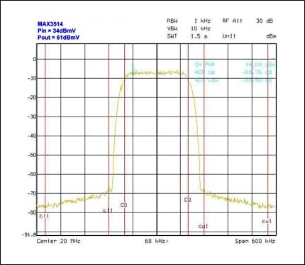
image 3.
Table 2. Correspondence between MAX3514 ACPR and output power and frequency
| Input (dBm) | GCW | Output (dBm) | Output (dBmV) | ACPR (dBc) | |
| 5MHz | -13 | 114 | 9.17 | 56.17 | -66 |
| -13 | 120 | 12.15 | 59.15 | -66 | |
| -13 | 122 | 13.14 | 60.14 | -66 | |
| -13 | 125 | 14.61 | 61.61 | -66 | |
| 20MHz | -13 | 114 | 9.1 | 56.1 | -66 |
| -13 | 120 | 12.1 | 59.1 | -65 | |
| -13 | 122 | 13.09 | 60.09 | -64.5 | |
| -13 | 125 | 14.56 | 61.59 | -63.4 | |
| 42MHz | -13 | 110 | 6.85 | 53.85 | -66 |
| -13 | 114 | 8.9 | 55.9 | -64.2 | |
| -13 | 120 | 11.87 | 58.87 | -62.9 | |
| -13 | 122 | 12.86 | 59.86 | -62.9 | |
| -13 | 125 | 14.32 | 61.32 | -61.2 | |
| 65MHz | -13 | 112 | 7.13 | 54.13 | -66 |
| -13 | 116 | 9.11 | 56.11 | -61.5 | |
| -13 | 122 | 12.04 | 59.04 | -59.8 | |
| -13 | 124 | 13.01 | 60.01 | -58.5 | |
| -13 | 125 | 13.5 | 60.5 | -58.2 |
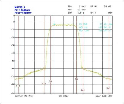
Figure 4.
Table 3. Correspondence between MAX3516 ACPR and output power and frequency
| Input (dBm) | GCW | Output (dBm) | Output (dBmV) | ACPR (dBc) | |
| 5MHz | -13 | 116 | 13.39 | 60.39 | -66 |
| -13 | 120 | 15.34 | 62.34 | -64.2 | |
| -13 | 122 | 16.31 | 63.31 | -63.8 | |
| -13 | 125 | 17.68 | 64.68 | -51.6 | |
| 20MHz | -13 | 116 | 13.41 | 60.41 | -66 |
| -13 | 120 | 15.38 | 62.38 | -64.4 | |
| -13 | 122 | 16.38 | 63.36 | -61.9 | |
| -13 | 125 | 17.74 | 64.74 | -51.2 | |
| 42MHz | -13 | 12 | 11.01 | 58.01 | -66 |
| -13 | 116 | 12.94 | 59.94 | -63.2 | |
| -13 | 120 | 14.9 | 61.9 | -61 | |
| -13 | 122 | 15.87 | 62.87 | -58.7 | |
| -13 | 125 | 17.23 | 64.23 | -48.7 | |
| 65MHz | -13 | 112 | 10.10 | 57.10 | -65 |
| -13 | 116 | 12.18 | 59.18 | -59.4 | |
| -13 | 120 | 14.11 | 61.11 | -57.7 | |
| -13 | 122 | 15.07 | 62.07 | -55.3 | |
| -13 | 125 | 16.42 | 63.42 | -47.4 |
Antenna For Automotive Product,Fm Transmitter Antenna,Radio Transmitter Antenna,Transmitting And Receiving Antenna
IHUA INDUSTRIES CO.,LTD. , https://www.ihua-coil.com