1 Main features and pin functions
CC1070 is a CMOS RF transmitter chip for narrow-band and multi-channel systems introduced by Chipcon Corporation. It can be used for automatic meter reading, safety warning, remote keyless login and tire pressure monitoring systems. It can also be used for other systems that require high sensitivity and selectivity. Wireless devices. The main features of CC1070 are as follows:
◠True monolithic RF transmitter, working frequency range is 402 ~ 470MHz, 804 ~ 940MHz?
â— Using low voltage power supply, the working voltage is 2.1 ~ 3.6V, and the output power is programmable;
â— Only few external components are required;
â— Small size (using QFN20 package);
â— With ASK, FSK and GFSK data modulation methods;
â— With on-chip VCO;
â— Comply with EN 300 220 standard and ARIB STD-T67 standard;
â— Can provide CC1070 development kit, the configuration data software is simple and easy to use.
figure 1
2 Working principle
Figure 1 shows a simplified diagram of the internal structure of CC1070. Only the signal pins are shown in the figure. During the transmission process, the radio frequency signal synthesized by CC1070 will be directly supplied to the power amplifier. The digital bit stream input from the D1 pin will be output using radio frequency shift keying. Furthermore, an internal Gaussian filter can be used for Gaussian frequency shift keying. The frequency synthesizer in the figure includes a complete on-chip LC voltage controlled oscillator. The operating frequency of the voltage controlled oscillator is 1.608 ~ 1.880GHz. CHP_OUT is the voltage output pin, and VC is the control node of the on-chip voltage-controlled oscillator. The loop filter is externally connected between CPC_OUT and VC. The crystal oscillator is connected between XOSC_Q1 and XOSC_Q2. The phase-locked loop is used to provide signals to LOCK. The four-wire SPI serial interface is used to configure the system. 
3 Application
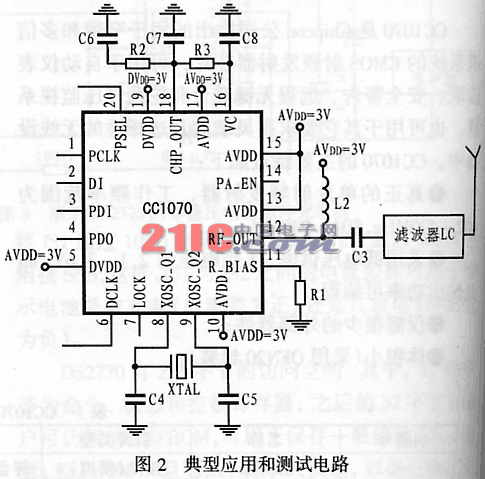
The typical application circuit of CC1070 is shown in Figure 2. It can be seen from the figure that using CC1070 to design requires only a few external components. Among them, L2 and L3 can match the transmitter with 50Ω. The accurate bias resistor R1 is used to set the accurate bias current. The loop filter includes two resistors? R2 and R3? And three capacitors? C6 ~ C8 ?; when higher loop bandwidth is required, C7 and C8 can be omitted; these values ​​can be used for data rates up to 4.8kbps Baud rate. External crystals with two load capacitors C4 and C5 are used as clocks. In some specific applications, some external devices can be added to improve performance. However, the power supply must be decoupled and filtered during design. The decoupling and filtering circuits are not shown in Figure 2. In fact, for narrow-band applications, the location and size of the decoupling capacitors, and power supply filtering are very important to obtain the best performance.
Single Arm Signal Pole,Camera Light Pole,Single-Arm Traffic Steel Pole,Traffic Signal Light Tube Pole
Jiangsu Baojuhe Science and Technology Co.,Ltd. , http://www.galvanizedsteelpole.com
