
Safety is the best line of Mercedes-Benz's car-making process. Next, we will discuss how the very important communication links in Mercedes-Benz safety are realized.
With the rapid development of functions such as camera system, distance control, route maintenance, and brake assist system, brake force distribution system, body roll intervention and mitigation system, the system functions of the car are no longer independent, but presented The relationship of mutual cooperation and the seamless integration between functions are the goals pursued by major OEMs. As the saying goes, how to protect the safety of these safety equipment is the practice of merging the muscles and skins, and practicing the sneak peek in the Mercedes-Benz commercial vehicles with various safety equipment. The following will analyze the fault-tolerant CAN from the communication system of the Mercedes-Benz commercial vehicle.
Introduction to Fault Tolerance CAN
Let's take a look at fault-tolerant CAN. The physical layer of fault-tolerant CAN is composed of three lines: CAN-H, CAN-L, and GND. Figure 1 below is a schematic diagram of the CAN bus communication signal:
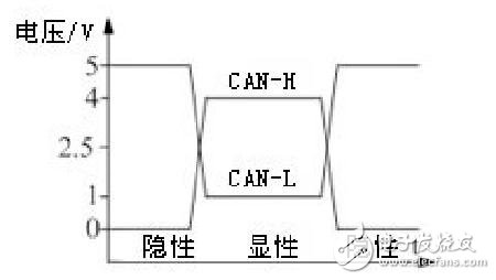
Figure 1 CAN bus communication signal
As can be seen from the figure, the amplitude of the voltage of CAN-H and CAN-L changes up to 4V when the recessive change occurs, which not only ensures the stable operation of the CAN bus under normal conditions, but also guarantees the CAN bus. When one of CAN-H and CAN-L fails (short circuit or open circuit), the fault-tolerant CAN transceiver will automatically recognize the bus status and make adjustment according to the bus status (see Table 1 below) to ensure that the CAN bus is faulty. The communication is normal.
Table 1 Fault status detection

Fault Tolerant CAN Fault Processing Simulation
Below we use CANScope with CANScope-StressZ to simulate CAN-H short-to-ground and CAN-L short-circuit bus communication. Figure 2 and Figure 3 show CAN-H short-to-ground and CAN-L short-to-ground. Wiring diagram.
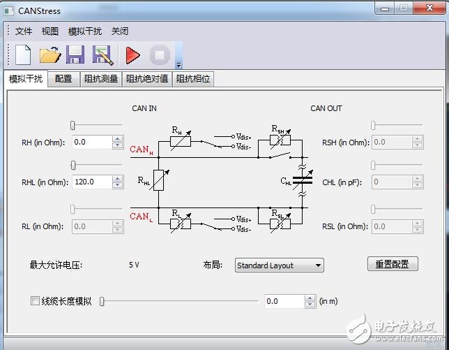
Figure 2 CAN-H short circuit to ground
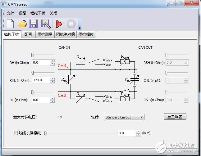
Figure 3 CAN-L short to ground
Figure 4 below shows the communication status of the fault-tolerant CAN in the case of analog CAN-H and CAN-L short-circuits read by CANScope:

Figure 4 Bus communication when CAN-H is shorted
Note: Although the fluctuation of CAN-H in the figure is large, the amplitude is very small~
We can see from Figure 4 that when the CAN-H is short-circuited, the data can still be read correctly by the receiving node, indicating that the CTM transceiver will automatically switch the working state to CAN-L and ground for CAN data transmission and reception. ;
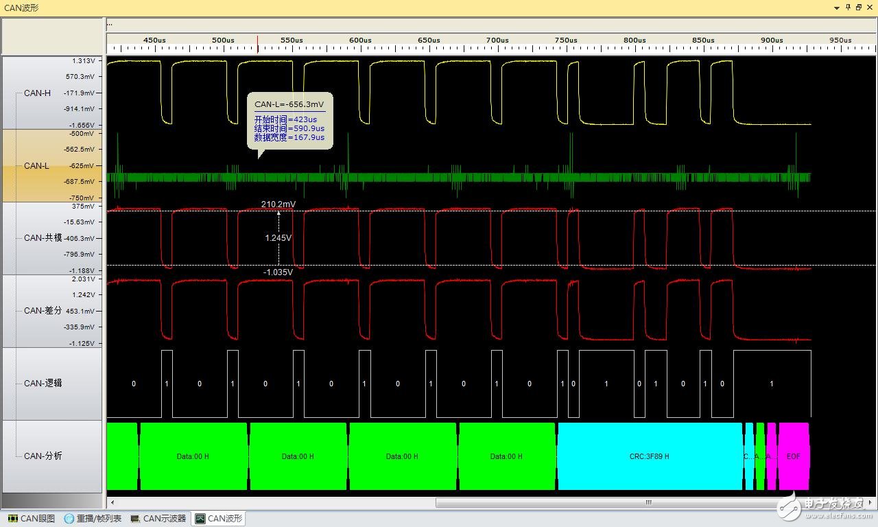
Figure 5 Bus communication when CAN-L is shorted
Similarly, when the CAN-L is short-circuited, the receiving node can also accurately analyze the CAN data, indicating that the CTM transceiver will automatically switch the working state to use CAN-H and ground to transmit and receive CAN data.
Through the above analysis, I believe that you will definitely feel that the fault-tolerant CAN can effectively guarantee the normal transmission and reception of CAN data in the case of short-circuit or open circuit of any line in CAN-H and CAN-L. Mercedes-Benz business The car is a large number of use of this fault-tolerant CAN bus, so that security has been greatly guaranteed!
Fault Tolerant CAN Network Topology
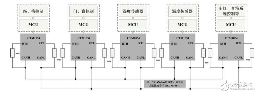
Figure 6 CTM1054 network topology and application examples
As shown in Figure 6, the CTM1054 network topology can connect up to 32 CTM1054 nodes in the same CAN-bus network. When connecting, you need to pay attention to the connection of the terminating resistor. The fault-tolerant CAN transceiver terminating resistor is set to 100 ohms: that is, all the resistances of CANH are connected in parallel to 100 ohms, and all the resistances of the CANL bus are connected in parallel to 100 ohms. Therefore, when constructing a CAN-bus network, the number of nodes that may exist in the CAN-bus network must be considered, and the terminal resistance value is calculated according to the number of nodes. As shown in the figure, there are five CTM1054 nodes, so the five resistance values ​​on the CANH are all For 500 ohms, the resistance of the five resistors on CANL is also 500 ohms.
Products Recommended
So what kind of transceiver supports fault-tolerant CAN? Here are two products that are recommended for you. These two products not only support fault-tolerant CAN functions, but also have other very powerful features:
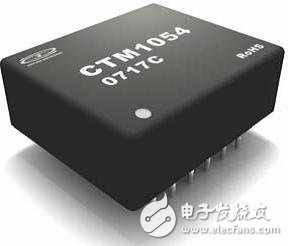
Figure 7 CTM1054 Fault Tolerant CAN Transceiver
The first one is the CTM1054 fault-tolerant isolated CAN transceiver based on years of experience in CAN-bus field application. It can eliminate the potential difference of the ground loop, effectively resist common mode interference, and protect the circuit of the CAN controller. In a strong interference environment, the probability of being disturbed and damaged is greatly reduced, and the user's overall design risk and procurement cost are reduced by modular design, reliable application and competitive price. As shown in Figure 7.
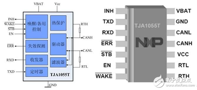
Figure 8 NXP TJA1055
The second is the TJA1055 from NXP, which uses a unique silicon-on-insulator (SOI) process technology that provides significant improvements in ESD, EMC, and power consumption. It also reduces the RF emission intensity, allowing users to expand the range of network connections without compromising security. Together with improved RFI performance and built-in slope control, you can reduce costs by using unshielded cables. As shown in Figure 8.
Harbour Marine Diesel Generator
Harbour Marine Diesel Generator,Onshore Marine Generator,Offshore Marine Generator,Marine Engine
Jiangsu Vantek Power Machinery Co., Ltd , https://www.vantekpower.com