
Abstract: This paper uses S3C6410 main control board, STM32, wifi module, GSM module and a variety of mobile terminals to design a smart home system, so that discrete devices form a mutual connection and coordinated operation through wireless and wired networks to achieve home environment monitoring. , anti-theft automatic alarm, automatic lighting control, gas leakage remote alarm and other functions, the use of good results.
With the development of science and technology and the improvement of people's living standards, people's requirements for safety, comfort and convenience of homes have gradually improved. Modern homes are developing towards a highly intelligent and humanized smart home. Smart Home, also known as Smart Home, is a networked and intelligent home control system that integrates automation control system, computer network system and network communication technology. As a new industry, smart home has huge potential for market consumption. This article takes Samsung S3C6410 processor as the core, and uses S3C6410 main control board, STM32, wifi module, GSM module and various mobile terminals to design a smart home system, which makes the discrete devices form a whole through wireless and wired media. Environmental monitoring, anti-theft automatic alarm, automatic lighting control, gas leakage remote alarm and other functions make the home safer, more comfortable and more convenient.
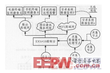
1 system overall scheme The overall structure of the smart home system is shown in Figure 1. It consists of four subsystems: data acquisition and automatic control system, data monitoring system, camera monitoring system and remote alarm system. The data collection sub-node sends the data to the centralized processing node through the wireless sensing module NRF24L01, and performs related automatic control tasks. The data of the centralized processing node is sent to the S3C6410 main control board for data processing through RS232; the local area network is established by using the wifi module. Send the data to the Android mobile terminal of the local area network; use the GSM module to send the alarm signal to the mobile terminal, and install the camera on the S3C6410 main control board, use the router to establish the local area network, and open the browser on the terminal to monitor the camera.
1.1 Data acquisition and automatic control system data acquisition and automatic control principle shown in Figure 2. The data acquisition and automatic control system collects and automatically controls the main parameters of the home environment (temperature and humidity, natural environment lighting state, gas state, infrared sensing state). The system includes three acquisition and automatic control nodes. The temperature and humidity are collected by the temperature and humidity sensor DHT11. The natural light state is detected by the photoresistor circuit. The gas state is detected by the smoke sensor module. The stairway condition is detected by the infrared sensor. The system has 3 nodes, and the node 1 includes the indoor temperature. Humidity collection, stairwell condition detection and stair light automatic switch control, kitchen smoke status detection and kitchen exhaust fan automatic switch control; node 2 has bathroom smoke detection and automatic control of exhaust fan; node 3 includes outdoor temperature and humidity Acquisition, detection of natural light conditions and automatic switching control of the yard lights. The data acquisition centralized processing node (wireless sensor module NRF24L01) collects the discrete node data, and a liquid crystal display is installed on the centralized node to display the collected temperature and humidity data, and is sent to the S3C6410 main control board through the serial port.
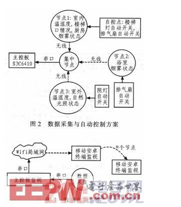
1.2 Data Monitoring System The data monitoring system has two types of terminals, namely the main control board display and the mobile Android terminal. The principle of data monitoring is shown in Figure 3. The S3C6410 uses the serial port to receive data from the data acquisition system and process it accordingly. The LCD panel is installed on the main control board to display the icons and data of the acquisition object. The application of the display screen is developed by the QT development tool C++ development language, and is called by the Linux system. The wifi module is installed on the main control board, and the wifi local area network is established through the module; the mobile Android terminal is loaded with the Android system, the monitoring application is designed by using the Eclipse development tool in the java language; the monitoring data is transmitted from the wifi module, within the local area network, Data monitoring can be performed as long as the local area network is connected.
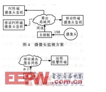
1.3 Camera Monitoring System The camera can be monitored on many devices as long as the device is equipped with a browser. The camera monitoring scheme is shown in Figure 4. The camera is installed on the main control board and driven by the program; here, the network data is transmitted by using the network cable or the wireless router to establish the data of the camera; the camera can be monitored by connecting the Internet cable to the computer, or the LAN established by the route can be monitored. At the same time, the LAN established by the route connection can be connected to the mobile terminal for monitoring. Multi-terminal monitoring, convenient and flexible.
1.4 Remote alarm system Gas is a hidden danger of home safety. Here, the GSM module and mobile terminal are used to establish a gas remote alarm system. The scheme is shown in Figure 5. When the gas leaks, the GSM module is triggered to notify the user to handle it in time.
2 System hardware design S3C6410 based smart home system consists of acquisition automatic control system and multi-terminal monitoring system; all nodes form a whole through wired medium and wireless network; main control board adopts S3C6410 with board and core board; main design of hardware In the data acquisition part, the data acquisition uses the STM32 processor, plus the peripheral sensors and control circuits.
2.1 Home temperature and humidity hardware design The core of the temperature and humidity acquisition module is the temperature and humidity collection. The integrated temperature and humidity sensor DHT11 is used. It should be noted that the digital output of the DHT11 is serial data. There is a specific data format, and the general IO port of the STM32 is required. To "simulate" this serial port to communicate with the DHT11.
2.2 Infrared state hardware design Infrared sensing system includes pyroelectric human body infrared module circuit and automatic light-on module circuit. The pyroelectric body infrared module circuit adopts the RE200B type pyroelectric human body infrared detecting head, and uses the special high-performance sensing signal processing integrated circuit BISS0001 to process the signal of the RE200B, and then transmits the signal to the STM32 for processing.
2.3 Natural illumination state Hardware design The natural light state data acquisition and automatic control system of the home includes two parts: the bright resistance detection circuit and the automatic light-on circuit. The light state detector uses a photoresistor sensor. When the illumination value does not reach the set requirement, the resistance value rapidly increases, so that the sensor circuit outputs a signal and automatically controls the light-on circuit. The signal collected by the photoresistor is connected to the STM32 via a zero-crossing comparator and processed by the STM32.
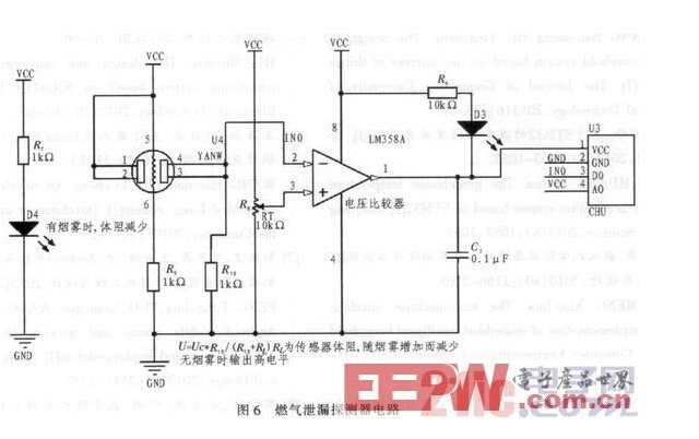
2.4 Gas Leakage State Hardware Design The home gas leak system consists of a gas leak detector circuit and an automatic switch exhaust fan control module circuit. The gas leak detector adopts the MQ-7 type gas sensor. When the component contacts the reducing gas, its conductivity increases rapidly with the increase of the gas concentration; it can be used for the detection of flammable gas. The hardware circuit of the gas leak detector is shown in Figure 6. The signal collected by MQ-7 is connected to STM32 through the zero-crossing comparator and processed by STM32.
3 system software design software system includes data acquisition and automatic control, main control board monitoring and Android monitoring. The acquisition data and the automatic control part are designed in C language on the KEIL platform; the main control board monitoring part uses the QT platform to design in C++; the Android monitoring part uses the Eclipse development tool to design in java language; these software systems realize acquisition, control, transmission, The function shown.
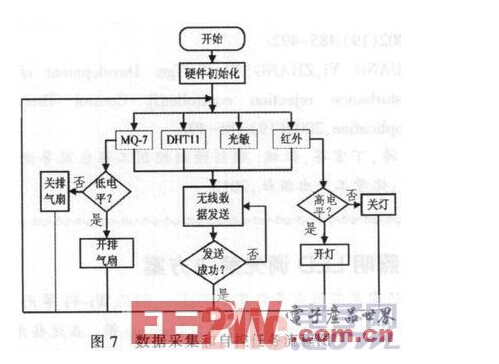
3.1 Collection data and automatic control system software design The home collection data section periodically collects temperature and humidity, infrared induction state, natural illumination state and gas state; the automatic control part includes real-time automatic control of yard lamp, exhaust fan and stair light. The software uses the keil development tool to design in C language. The data acquisition and self-control task flow chart is shown in Figure 7.
3.2 Main Control Board Monitoring System Software Design The main control board periodically receives data from the data acquisition part and performs display, control, and transfer tasks. These tasks are completed by software. The software uses the QT platform to design in C++ high-level languages ​​and is called with the Linux system. The system will automatically transfer the data and display it on the LCD screen. At the same time, the display icon will change according to the data. If the gas leaks, an audible alarm will be issued.
3.3 Android monitoring software design Android terminal receives the data transmitted from the main control board by connecting to the wifi local area network; the software design uses the Eclipse development tool to design in java language; the software can display the received data on the display of the Android device. If the gas leaks, an audible alarm will be given.
4 System design considerations System design should pay attention to the following issues: 1) When using STM32, because the IO port used is more, the software configuration IO port should pay special attention to correctly configure its mode. 2) Because there are more IO ports used, there are more program processing parts. Pay special attention to check to avoid overlapping multiple functions using the same IO port. 3) When using the wireless transceiver module NRF24L01, write the receive channel address, P0 and P1 channels are 40-bit addresses, but P2-P5 has only 8-bit address, and its high 32-bit address is the same as the P1 channel, so just write a byte address. can. 4) Remember that the mode sent and received when configuring the NRF24L01 wireless transceiver cannot be confused, and the transmission and reception frequency should be the same. 5) Configure the kernel to be patient and careful, otherwise it will be a problem. 6) STM32 is a small chip with a small pin. Pay special attention when soldering the chip. 7) Each sensor should adjust its sensitivity before use, otherwise it will not be tested.
5 Conclusion The application of S3C6410 main control board, STM32, wifi module, GSM module, various mobile terminals, etc. to design a smart home system, so that discrete devices through the wireless and wired media to form a whole, so that it has home environment monitoring, multi-terminal Camera surveillance, automatic lighting control, gas leak remote alarm and other rich features, really make users feel safe, comfortable and convenient at home.
Best Tire Inflator For Trucks,Truck Tire Pump,Air Pump For Truck Tires,Portable Truck Tire Inflator
SHENZHEN SMARTNEWO TECHNOLOGY CO,. LTD , https://www.newopump.com