
introduction
In many electronic systems, it is necessary to provide bipolar (positive and negative) voltage or current for a particular type of load. Loads that require bipolar voltage/current include FPGA body bias applications, thermoelectric coolers, DC motors, and many other types of applications.
There are many traditional methods to provide bipolar voltage/current to the load. H-bridge designs are often used, but both terminals of the load are not directly grounded. Both terminals of the load must swing between the positive supply rail and ground. To filter out this chopping waveform, an inductor is usually placed in series with the load. The fact that the load cannot be grounded directly can complicate the mechanical and electrical design of the entire system. The H-bridge approach also requires four switch components and more sophisticated control methods. Some loads have negative terminals that cannot be applied with high bias (relative to ground), such as FPGA reverse bias applications.
Another traditional method is to create two power rails, one for the rail and one for the rail. People use a variety of different circuits to "switch off" in a regulated positive or negative rail to achieve bipolar operation where the voltage can be below ground. This results in a very complex system that is generally less efficient and produces a non-linear response when the output voltage crosses ground.
This article presents a new DC/DC switch architecture that enables true 4-quadrant operation, which means that the output voltage can be positive or negative and current can flow in both directions. In addition, the output voltage generated by this new architecture can be smoothly converted from one polarity to another, through ground potential, and this conversion mode does not create any nonlinear problems.
Four quadrant DC/DC converter
Figure 1 shows the basic connections and components of this 4-quadrant converter. NFET (MN) and PFET (MP) operate between inverting and constant switching frequency. Current mode control (not shown) is used to modulate the duty cycle of the MN when needed.
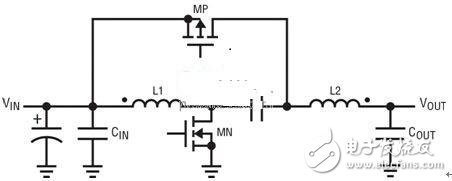
Figure 1: Four-quadrant DC/DC converter topology
If we assume that the circuit is operating at a fixed frequency, then the duty cycle of the MN turn-on time can be calculated as follows:
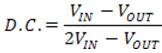
It can be clearly seen from this equation that when the VIN voltage is positive, the output voltage VOUT can be positive (highest VIN) or negative (limited only by the actual DC factor), or 0V. Actually, 0V The output level is nothing special, because at this operating point, the duty cycle of the converter DC is 50%.
Regardless of the polarity of the output voltage, the output of the converter can sink or supply current, making this circuit a true topology for operation in 4 quadrants. The highest drain-to-source voltage on both MN and MP is 2VIN–VOUT. For example, if VIN is +12V and VOUT is -12V, then the BVDSS rating of both FETs must be higher than 36V.
LT8710 in four-quadrant topology
Linear Technology's recently introduced controller, the LT8710, is available in a 4-quadrant topology. Figure 2 shows a complete circuit configured for this topology, which has been thoroughly tested. The input voltage for this circuit is typically 12V, but the allowable range is 11V to 13V. The output is adjustable from +5V to -5V with an output current of ±3A. The analog control signal, VCNTL, is used to regulate the output voltage. The LT8710 is an 80V controller that can be used to form many other quadrant converters that offer higher or lower voltages and currents.
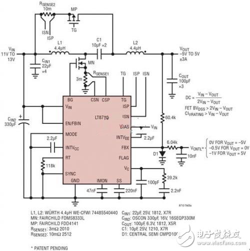
Figure 2: 4-quadrant converter with LT8710
The converter's 4-quadrant operating capability is shown in Figure 3. The sinusoidal control signal is used to generate a sinusoidal output voltage centered at 0V. The inductor current can be positive or negative, and whether it is negative or not, the output voltage must be at the desired value. These operating waveforms show that the converter works cleanly and smoothly across ground potential. Using a sine wave control signal is an arbitrary choice, and a DC signal, a square wave signal, or any other type of signal can be used.
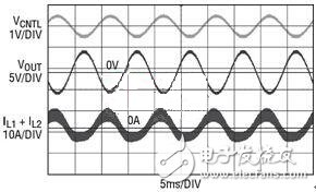
Figure 3: Sine wave output voltage through 0V
application
There are many applications that can take advantage of this 4-quadrant DC/DC converter. In high performance digital circuits such as FPGAs, body reverse bias can be used to significantly reduce static power while maintaining or improving dynamic performance. The body voltages of the PMOS and NMOS devices can be independently controlled to adjust the device's threshold (VT). When the FPGA requirements are low, the threshold can be adjusted higher, significantly reducing the leakage current in these digital components. When the FPGA requirements are high, the threshold can be lowered to increase speed and thus improve FPGA performance. Figure 4 shows a high level block diagram of one such application. Note that for NMOS body bias, the voltage is typically 0V ± 300mV, which is ideal for four-quadrant topologies.
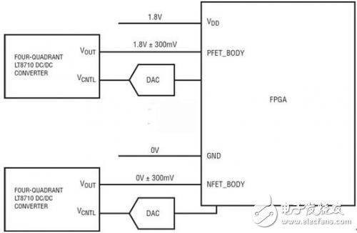
Figure 4: FPGA Body Bias Application
Another application that can benefit from the 4-quadrant topology is the DC motor driver. In many cases, DC motors require speed regulation and reverse capability. The LT8710 for 4-quadrant converters meets both requirements. Figure 5 shows one such application. Note that the negative terminal of the DC motor can be simply connected to ground and the positive terminal can be adjusted between positive and negative 10V. Similar to DC motor drive applications, the 4-quadrant topology can also be used to drive thermoelectric coolers (TECs), audio speakers, and many other applications.
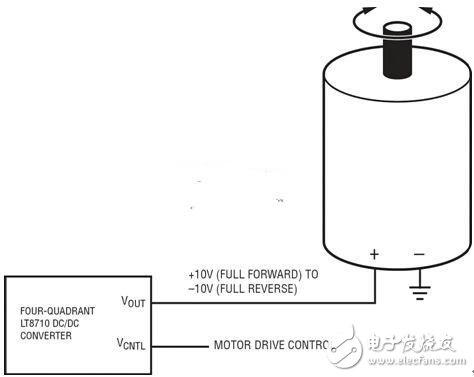
Figure 5: DC motor drive with reversible drive direction
in conclusion
The LT8710 for 4-quadrant DC/DC converter topologies is a powerful circuit device that produces positive and negative output voltages as well as positive and negative output currents. The inductor in series with the output (L2 in Figure 2) reduces the output voltage ripple. The process of producing an output voltage close to ground is also simplified because in this case the duty cycle is close to 50%. Many applications can benefit from this circuit, including but not limited to FPGA body bias, DC motor drive, and thermoelectricity. Cooler and audio driver.
Food Choppers :
Food Choppers are small kitchen appliance that break up all kinds of chunks meat into minced meat. Besides, food choppers can also be used to chop peanuts, onions, garlic, spices and other foods. Food choppers including Plastic Bowl Choppers, Glass Bowl Choppers and Stainless Steel Bowl Choppers. And food choppers can also be divided into 0.6L choppers, 1.2L Choppers , 1.8L Choppers according to different capacities.

Advantages of food choppers:
1. Stylish appearance.
2. Runs smoothly and efficiency.
3. Easy to disassemble and easy to clean.
4. Rugged and inexpensive
Weclome to send us any inquiry for more details.
Food Choppers
Food Choppers,Electric Food Chopper,Meat Chopper,Mini Food Chopper
Flying Electronic Co., Ltd , https://www.flyingelectronic.com