
Application Design and Implementation of DTMB Receiver Chip
With the gradual popularization of DTMB applications, the complexity of urban ground wireless signal transmission has begun to manifest itself, and higher demands have been placed on the receiving chip. As the most critical part of the DTMB receiver, the performance of the receiving chip directly determines the reception effect of the whole machine and the popularity of terrestrial digital TV. Hangzhou Guoxin took the lead in launching the first domestic three-mode demodulation receiver chip integrating DTMB single-carrier / multi-carrier and cable digital TV in March 2008, which has been widely used in Hong Kong, Hangzhou, Jingmen, Hunan and other markets Designing a chip that meets the domestic receiving environment has enough experience and full understanding.
Advantages of DTMB standard
DVB-T is the most widely used terrestrial digital TV broadcasting standard in the world. It has a history of 13 years from its birth to the present. It is also the most widely used terrestrial digital TV standard in China before the DTMB standard. Although the technology of DVB-T is very mature, the requirements for digital TV reception in the past 10 years have changed significantly compared to that time. In addition, the large-scale integrated circuit industry has also experienced rapid development, making more advanced technologies available. Used in the receiving chip. DTMB is a new generation digital TV transmission standard, which has the following advantages compared to DVB-T:
1. Higher spectrum utilization. DTMB adopts TDS-OFDM modulation method, without using pilot frequency for channel estimation. Compared with DVB-T, spectrum utilization is improved by about 10%, and more TV programs can be sent under the same transmission bandwidth.
2. Better signal coverage. Terrestrial digital TV uses a wireless signal transmission method, which is susceptible to signal attenuation and other wireless signals. FEC (Forward Error Correction Code) in DTMB is a combination of LDPC (Low Density Check Matrix Code) and BCH code, which has a lower signal-to-noise ratio threshold than the combination of DVB-T convolutional code and RS code. Therefore, the signal coverage under the same transmission power is greatly improved.
3. Better mobile reception ability and anti-interference ability. The subcarrier spacing of DTMB's multi-carrier mode is equivalent to the 4K mode of DVB-T (applied in DVB-H). From the perspective of channel estimation, it has the maximum theoretical anti-Doppler frequency deviation capability that meets the Nyquist criterion At around 900Hz, converted to a signal frequency of 704MHz, the theoretical speed of more than 1300 kilometers can be reached. In addition, because it has a maximum interleaving depth of 250ms, it also greatly improves the ability of DTMB to resist burst interference and shadow fading.
Deficiency of DTMB standard
Compared with the DVB-T standard, the disadvantage of the DTMB standard is that the cyclic prefix structure used by DVB-T makes it able to resist echo interference up to 224? S, while the multi-carrier mode of DTMB can only reach 125? s (frame mode 3). From the analysis of the PN sequence characteristics of the DTMB frame header, only when the echo length is less than 57.4? S (corresponding distance is 17.2Km) can the reception performance be guaranteed to be in an optimal state. If the echo length is greater than 57.4 μs, although the channel estimate has a maximum spread-spectrum gain of 20 dB, once the number of echoes increases (as shown in Figure 1), the interference between the echoes increases and the gain caused by the channel estimate will drop sharply , In extreme cases even negative values ​​will appear. DTMB's single-carrier mode, because it uses time-domain equalization technology to eliminate the effect of echo, is less sensitive to echo length, and can resist echo interference of nearly 300? S in our design. This article will not focus on description .
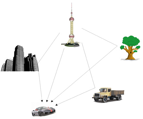
Figure 1. Ground signal echo interference.
High performance DTMB receiver chip
For the forward echo and multipath Doppler interference mentioned by most designers, the DTMB reception capability is reduced. According to our research, if all echo delays are less than 57.4? S, use reasonable frame header area detection The algorithm, regardless of the characteristics of the echo distribution, the channel estimation gain is very high. At this time, the signal coverage is mainly determined by the signal field strength. In general, Doppler interference introduced by vehicle movement cannot cause reception failure. After theoretical derivation and field testing, when MFN (multi-frequency network) is used and the echo delay range is within 30 μs, the reception quality is only related to the signal field strength.
Long-path multipath echoes are more common in SFN (Single Frequency Network). In order to effectively cover a large area and conduct reasonable frequency planning, SFN is usually used to lay out the network. According to the previous analysis, when the two towers are more than 17.2Km apart, it will be easy to have strong echoes with a delay of more than 57.4? S, plus many dense multipath echoes introduced by the reflection of other objects (such as tall buildings, water surface) In the case of waves, it is often the case that the field strength is sufficient, but normal reception is not possible. This is also the reason why some cities still cannot achieve better reception after completing signal coverage. In addition, in the process of vehicle mobile reception, the number and position of echoes are prone to drastic changes, which can easily lead to the DTMB receiver frame header detection module cannot be accurately positioned, which in turn affects the channel estimation and tracking changes in the receiving environment in time, reducing the Mobile reception effect.
It can be seen from the above analysis that in mobile reception and complex multipath echo environments, the accuracy of frame header detection is crucial. GX1501B uses a frame header detection mechanism specially optimized for SFN, which can accurately locate the strongest signal. The main path position and numerous echo ranges provide the most effective data for the channel estimation module. The channel estimation module uses a unique iterative algorithm to make full use of the data of each echo to improve the accuracy of channel estimation. Combined with the design of the time domain / frequency domain joint equalization, no matter whether it is C = 1 single carrier mode, The multi-carrier mode of C = 3780 can provide superior anti-echo performance, which fully compensates for the decline in the receiving capacity of the urban receiving environment due to the introduction of tall buildings, water reflections, and the introduction of multiple transmission towers and patch repeaters. This also makes GX1501B the DTMB receiving chip with the best overall comprehensive receiving performance.
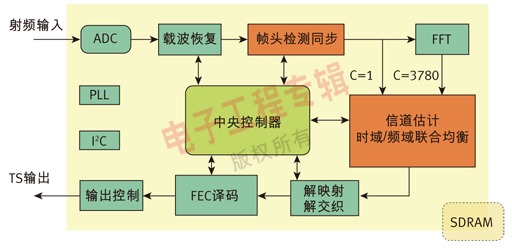
Figure 2. Guoxin GX1501B DTMB receiver chip structure diagram.
Porcelain Station Post Insulator according to IEC, ANSI and other standards are used in substations and related switching equipment. Station Post Ceramic Insulator are produced in single piece up to 2300 mm and can operate voltages up to 1100KV in stacked configuration. High Voltage Station Post Insulator are subjected to compression, cantilever and torsional loads during service. Station Post Insulator for high voltagr use semiconductor glazes, so you don't have to worry about salt deposits or corona discharges.
Product Description
1.Material: Porcelain
2.Improved contamination performance
3.Widely applied to the line of different voltage classes
4.With features of good insulation performance
5.Long lasting durability
| MAIN DIMENSIONS AND STANDARD PARTICULARS | |
| Type | C4-125 |
| Creepage distance(mm) | 430 |
| Dry arcing distance(mm) | 200 |
| Cantilever strength(KN) | 4 |
| Tension Strength(KN) | 38 |
| Torsion strength(N.m) | 800 |
| Power frequency flashover wet voltage(KV) | 50 |
| Impulse withstand voltage(KV) | 125 |
| Net weight(KG) | 9 |
| MAIN DIMENSIONS AND STANDARD PARTICULARS | |||
| ANSI Class | TR-205 | TR-208 | TR-210 |
| Creepage Distance/mm | 394 | 610 | 940 |
| Cantilever Strength/kn | 8.9 | 8.9 | 8.9 |
| Tensile Strength/kn | 38 | 44.5 | 53 |
| Torsional Strength/k.m | 791 | 904 | 1130 |
| Compression Strength/kn | 44.5 | 44.5 | 66.7 |
| Low Frequency Dry Flashover Voltage/kv | 85 | 110 | 145 |
| Low Frequency Wet Flashover Voltage/kv | 55 | 75 | 100 |
| Critical Impulse Flashover Voltage, Pos/kv | 125 | 170 | 225 |
| Critical Impulse Flashover Voltage, Neg/kv | 200 | 250 | 290 |
| Low Frequency Dry Withstand Voltage/kv | 50 | 70 | 95 |
| Low Frequency Wet Withstand Voltage/kv | 45 | 60 | 80 |
| Impulse Withstand Voltage/kv | 110 | 150 | 200 |
| Net Weight/kg | 7 | 11 | 16 |
| Applicable Standard | ANSI C29.9 | ANSI C29.9 | ANSI C29.9 |


We warmly welcome friends both domestic and abroad to visit our company, if you have any questions, please contact with us directly.
Station Post Insulator
Station Post Insulator,Station Post Ceramic Insulator,High Voltage Station Post Insulator,Post Insulator For High Voltage
FUZHOU SINGREE IMP.& EXP.CO.,LTD. , https://www.cninsulators.com