1 Road lighting is an important part of urban and rural construction, playing an important role in creating a good environment, social security, cloudy weather and night traffic safety. China's street lighting project has developed rapidly, and the power consumption has increased sharply. At the same time, it has also aggravated the increasingly tight energy supply and demand contradiction.
With the promulgation and implementation of the National “Energy Conservation Law†and the requirements of China’s “Eleventh Five-Year Planâ€, energy conservation has been incorporated into the important content of the social sustainable development strategy. Nowadays, most of the street lighting is directly powered, and manual power is turned off manually.
In order to improve the management level of the street lamp system and meet the road lighting requirements, intelligent on-demand, energy-saving lighting and single street lamp monitoring are more suitable for small-scale applications (such as schools, factories, villages, etc.). Aiming at this, a low-cost and high-reliability NRF9E5-based wireless street light control system is proposed to realize on-demand illumination and monitoring alarms for street lamps. This control method avoids the complexity and uncertainty of interference in power line carrier communication, greatly improves the stability and certainty of control communication, and is more suitable for small-scale applications, and is highly feasible.
2 wireless street light control system structure
The no-line lamp control system is composed of a main control node connected to the PC and a plurality of street lamp control nodes, as shown in FIG. The working information of the street lamp is set by the lower computer, such as the clock calendar, the switching time, etc., the working state of each street lamp can be visualized by the upper computer; the main control node transmits the command information to the street light node, and the wireless jump transmission is performed between the nodes; the street light node routing Control information and alarm for street lamp failure; if a street lamp node fails, cross the node to communicate and feed this message back to the control center. The two nodes communicate through a handshake protocol to ensure that the message is sent out.
3 system hardware design
3.1 main control node design
Main control node design: RF soc chip nRF9E5, light intensity sensor ISL29000, USB TO RS232 interface conversion chip PL2303 and program storage unit 25AA320, as shown in 2.
The nRF9E5 is a Nordic VLSI system-level RF chip with a built-in nRF905 433/868/915MHz transceiver, a 051-compatible microcontroller and a 4-input 10-bit 80ksps A/D converter. The transceiver consists of a complete frequency synthesizer. It consists of a power amplifier, a regulator and two receivers, which are suitable for the design of wireless data transmission systems. The nRF9E5 also has a carrier detect function.
In the ShockBurstTM receiving mode (which is a type of transceiver used by Nordic to save energy in RF transceivers), the carrier detect pin is set high when the RF carrier in the nRF9E5 working channel appears. This feature nicely avoids collisions between packets from different transmitters at the same operating frequency.
The ISL29000's operating illuminance ranges from 1 lux to 10000 lux, which converts illuminance into current. The output current is proportional to the brightness of the photodiode. The output current is converted to voltage by an external resistor and is calculated by a 10-bit ADC of the RF soc chip nRF9E5. The visibility of the external environment makes a judgment on whether to open or close the street light. The PL2303's USB mass transfer mode, large data buffer and automatic flow control are used to complete communication with the PC. The clock calendar of the main control center can be adjusted and set by the PC, and the street lamp working status of each node collected by the main control node nRF9E5 is displayed on the PC interface, which is convenient for grasping the working state of each street lamp.
3.2 Design of street lamp node
Street lamp node design: RF soc chip nRF9E5, program memory unit 25AA320, lamp operating voltage and current detection and relay control switch, as shown. The MCU detects the current of the lamp through the transformer T1 to judge that the lamp works in the normal/fault state. The feedback information is sent to the control center through the wireless transceiver module nRF905, and the control command sent by the master control center is also received through the wireless transceiver module nRF905. Relay Z1 controls the switch of the lamp.
4 system software design
4.1 Communication Protocol
Each node in the system has data collection and routing functions. In order to distinguish whether the data is from the master node or the street light node, the received data is the command information or the node light work information, and the ad hoc protocol is as shown.
Preamble is the boot byte, Add is the pick-up address, and Payload is the valid load data (including the destination identification code Rxid, the local transmission identification code Txid, the source transmission identification code Sid and the Data word: when the word S=00 is selected, Data is the set clock calendar and street light breaking time; when S=01, Data=1 indicates abnormal weather street light on command, Data=0 indicates abnormal weather street light off command; when S=10, Data is alarm address light address information. When S=11, Data is the address information of the node failure alarm), and CRC is the check code.
4.2 program design
(1) The clock calendar and the opening and closing time of the street lamp are set by the PC, and the main control node jumps to each street lamp node through the node, and the street lamp node routes the information, so that the clock of the main control node and the street lamp node are synchronized, and the street lamp node It can automatically open and close at the set time.
(2) In the bad weather, when the main control node detects the decrease in visibility, the control information is transmitted to each street light node, and the street light is turned on.
(3) If a street lamp is damaged, the street lamp node detects the information and routes it through other street lamp nodes, and transmits it to the main control node via the upper computer for alarm.
(4) When the street lamp node routing information, if a node fails, the node is detected to be invalid by the handshake protocol, the information is automatically transmitted over the node, and the message is transmitted to the main control center for alarm.
It is the spectrum diagram of the oscillation wave when the wireless module works. It can be seen that the center frequency of the node operation is f=433.2MHz, the abscissa is the frequency, the unit is 500kHz, the coverage is 5MHz, and the ordinate is the signal strength, which is -0.46dBm at the center frequency point. For testing, let the transmitter transmit a constant carrier. To do this, you must keep TRX_CE high instead of a pulse. In addition, automatic resend must be disabled. When the data pulse is transmitted, the transmitter will continuously transmit the unmodulated carrier.
It is a schematic diagram of the upper computer, with 5 street lights analog control, the status of each parameter is indicated in the figure. Through the host computer, clock synchronization of each street lamp node, setting of street lamp opening and closing time, street lamp working condition monitoring and abnormal weather alarm can be performed.
5 Conclusion
Through the research of the wireless street lamp control system based on nRF9E5, the automatic control of street lamps is realized, which plays an active role in energy saving, abnormal weather lighting and street lamp failure alarm. In the system, the node skip transmission, the transmit-receive handshake protocol and the communication protocol of the self-correction node are adopted, and the transmission distance is up to 800m, the communication reliability is high, but the communication speed is relatively low, which affects the response speed. In order to improve the communication speed and reliability, a one-to-many jump transmission is being tested.
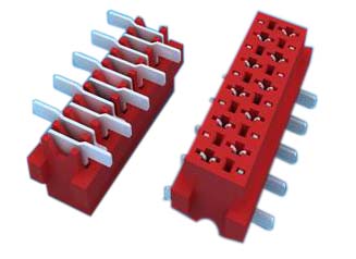
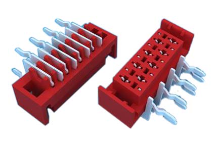
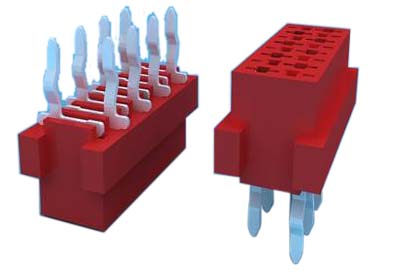
1.ANTENK Insulation Displacement termination connectors are designed to quickly and effectively terminate Flat Cable in a wide variety of applications. The IDC termination style has migrated and been implemented into a wide range of connector styles because of its reliability and ease of use. Click on the appropriate sub section below depending on connector or application of choice.


SPECIFICATION
Current Rating: 1.0Amp
Insulation Resistance: 1000MΩ min
Contact Resistance: 20mΩ max
Withstand Voltage: 500V AC/DC
Operating Temperature: -40°C to +105°C
Contact Material: Phosphor Bronze
Contact Plating: Au Over Ni
Insulator Material: High Temperature plastic UL94V-0
Ribbon Cable Connectors,Cable Connector,Cable Assembly,Connector Flat Ribbon Cable,Box Header Connector,Latch Header Connector,IDC Socket Connector,Dip Plug Connector
ShenZhen Antenk Electronics Co,Ltd , https://www.antenkelec.com
