
The transient voltage suppressor is a high-performance protection device in the form of a diode with extremely fast response time and high surge absorption capability. When the two ends of the TVS are subjected to the reverse transient overvoltage pulse, the high impedance between the two ends can be changed to a low impedance at a very high speed to absorb the instantaneous large current and clamp the voltage to a predetermined value, thereby effectively protecting Components in the circuit are protected from damage. This paper describes the main characteristic parameters and selection considerations of TVS devices, and gives the application method of TVS in circuit design.
This article refers to the address: http://
1 TVS device characteristics and main parameters
1.1 TVS device characteristics
Under the specified reverse application conditions, the TVS is in a high impedance state for the protected line. When the instantaneous voltage exceeds its breakdown voltage, the TVS provides a low-impedance path and shunts the instantaneous current flowing to the protected component to the TVS diode through a large current method, while limiting the voltage across the protected component to The clamping voltage of the TVS. When the overvoltage condition disappears, the TVS returns to a high impedance state. Compared with ceramic capacitors, TVS can withstand a voltage of 15 kV, but ceramic capacitors have a weaker bearing capacity. A 5 kV shock will cause approximately 10% of the ceramic capacitor to fail, and at 10 kV, the damage rate will be as high as 60%.
1.2 Main parameters of TVS devices
(1) Minimum breakdown voltage VBR
When the TVS flows through a specified current, the voltage across the TVS is called the minimum breakdown voltage, in which the TVS is a low impedance path. Below 25 ° C, below this voltage, TVS will not avalanche breakdown.
(2) rated reverse shutdown voltage VWM
VWM is the voltage that TVS can withstand under normal conditions. This voltage should be greater than or equal to the normal operating voltage of the circuit being protected. But it also needs to be as close as possible to the normal working voltage of the protected circuit, so that the entire circuit will not face the overvoltage threat before the TVS works. According to the dispersion of VBR and standard value of TVS, VBR can be divided into 5% and 10%. For 5% VBR, VWM=0.85VBR leg; for 10% VBR, VWM=0.81 VBR.
(3) Maximum peak pulse current IPP
IPP is the maximum pulse peak current that the device is allowed to pass under specified pulse conditions when the TVS is operating in the reverse state.
(4) Clamping voltage Vc
When the pulse peak current Ipp flows through the TVS, the maximum voltage value appearing at both ends thereof is referred to as a clamp voltage Vc. Vc and Ipp reflect the surge suppression capability of TVS. The ratio of Vc to VBR is usually referred to as a clamp factor (coefficient), and its value is generally between 1.2 and 1.4. In actual use, the Vc should be no larger than the maximum allowable safety voltage of the protected circuit, otherwise the protected device will be damaged.
(5) Maximum peak pulse power consumption PM
The PM is usually the product of the maximum peak pulse current Ipp and the clamp voltage Vc, that is, the maximum peak pulse power consumption. It is the maximum peak pulse power consumption that TVS can withstand. At a given maximum clamping voltage, the greater the power consumption PM, the greater the surge current capability. In addition, peak pulse power consumption is also related to pulse waveform, pulse duration, and ambient temperature. Moreover, the transient pulses that TVS can withstand are not reproducible.
(6) Capacitance C
The capacitance of the TVS is determined by the cross-sectional area of ​​the silicon and the bias voltage, which is measured at a specific frequency of 1 MHz. The size of C is proportional to the current carrying capacity of the TVS, and C is too large to attenuate the signal. Therefore, the capacitance C is an important parameter for the TVS of the data interface circuit.
(7) Leakage current IR
IR is the leakage current of the TVS tube when the maximum reverse operating voltage is applied to the TVS. This leakage current IR is an important parameter when TVS is used in high impedance circuits.
2 Note on the use of TVS
When TVS is selected, the following main factors should be considered according to the specific conditions of the circuit:
First, since the bidirectional TVS can absorb the instantaneous large pulse power in both the forward and reverse directions, the voltage is clamped to a predetermined level. Therefore, if the circuit is likely to withstand surge voltage surges from both directions, a two-way TVS should be used. Bidirectional TVS is generally suitable for AC circuits, and unidirectional TVS is generally used for DC circuits. In addition, the clamp voltage Vc is not greater than the maximum allowable safe voltage of the protected circuit.
Second, the maximum peak pulse power consumption PM must be greater than the maximum transient surge power present in the circuit. However, in practical applications, surges may occur repeatedly, in which case even if the individual pulse energy is much smaller than the pulse energy that the TVS device can withstand, if repeated application, these individual pulses The accumulation of energy may also exceed the pulse energy that TVS devices can withstand in some cases. Therefore, in circuit design, the appropriate TVS device must be carefully considered and selected at this point so that the cumulative application of pulse energy does not exceed the pulse energy rating of the TVS device during the specified interval.
Third, in the actual application process, the maximum reverse operating voltage must be correctly selected. The general principle is to select the maximum reverse operating voltage of the TVS tube by 1.4 times the AC voltage. The DC voltage is selected from 1.1 to 1.2 times to select the highest reverse operating voltage of the TVS tube.
3 TVS typical application in circuit design
In practical application circuits, the best way to handle transient damage to the device is to direct the instantaneous current away from the sensitive device. To achieve this, the TVS is connected in parallel with the protected line on the board. Thus, when the instantaneous voltage exceeds the normal operating voltage of the circuit, the TNS will avalanche breakdown, providing an ultra-low impedance path to the instantaneous current, with the result that the instantaneous current is diverted through the TVS, thereby avoiding the protected device, and Keep the protected circuit at the off voltage until the voltage returns to normal. After that, when the instantaneous pulse ends, the TVS diode automatically returns to the high-impedance state, and the entire loop enters the normal voltage state. The following are some typical examples of TVS in circuit applications.
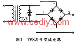
3.1 TVS application in AC circuit
Figure 1 shows an application circuit for a bidirectional TVS in an AC circuit. The application of TVS can effectively suppress the overload pulse brought by the power grid, thereby protecting the rectifier bridge and all components in the load. The TVS clamp voltage in Figure 1 should not be greater than the maximum allowable voltage of the circuit.
3.2 Protecting DC stabilized power supply with TVS
Figure 2 is a DC stabilized power supply with a TVS at its regulated output to protect the instrumentation that uses the power supply, while also absorbing the peak-to-emitter voltage across the transistor in the circuit to protect the transistor. It is recommended to add a TVS tube to the output of each regulated source, which can greatly improve the reliability of the whole machine.

3.3 Protecting transistor circuits with TVS
Various transient voltages can damage the EB junction or CE junction of the transistor, especially when the collector of the transistor is inductive (coil, transformer, motor) load, usually produces a high voltage back EMF, which may damage the transistor. In practical applications, TVS is recommended as a protection device. Figure 3 shows four circuit examples of TVS protection transistors.

3.4 Protection of integrated circuits
Since the integration of modern ICs is getting higher and higher, and the withstand voltage is getting lower and lower, it is easily damaged by the impact of transient voltages, so protection measures must be taken. Generally, there are protection networks at the input and output of the CMOS circuit. For the sake of reliability, various protection networks have been added to the external interfaces of the whole machine. Figure 4 shows the circuit measures for protecting TTL and CMOS devices with TVS.
3.5 Protection of integrated operational amplifiers with TVS
The integrated op amp is very sensitive to external electrical stresses. Therefore, in the process of using an op amp, if an operation error occurs or an abnormal working condition is taken, excessive voltage or current, especially a surge and an electrostatic pulse, may occur, which may easily damage the operational amplifier or Invalid. Figure 5 shows the protection circuit for preventing overvoltage damage at the input of the op amp differential mode with TVS.

4 Conclusion
This paper mainly describes the characteristics and main parameters of TVS devices, as well as the precautions when selecting devices. At the same time, the typical application circuit of the device in circuit design is given, in order to deepen the understanding of TVS by circuit designers and design high reliability. The application circuit provides the basis. Although the current application of TVS in China is in the promotion stage, we have reason to believe that TVS devices will eventually become more widely as more and more designers become more aware of TVS and the excellent performance of TVS. Applications.
Optical fiber jumpers are used to make jumpers from equipment to optical fiber cabling links. There is a thicker protective layer, which is generally used in the connection between the optical transceiver and the terminal box, and is used in some fields such as optical fiber communication systems, optical fiber access networks, optical fiber data transmission, and local area networks.
Optical fiber jumper (also known as optical fiber connector) means that both ends of the optical cable are equipped with connector plugs to realize the active connection of the optical path; one end with a plug is called a pigtail. Optical Fiber Patch Cord/Cable is similar to coaxial cable, except that there is no mesh shielding layer. In the center is the glass core through which light propagates. In a multimode fiber, the diameter of the core is 50μm~65μm, which is roughly equivalent to the thickness of a human hair. The single-mode fiber core has a diameter of 8 μm to 10 μm. The core is surrounded by a glass envelope with a lower refractive index than the core to keep the optical fiber in the core. On the outside is a thin plastic jacket to protect the envelope.
The classification and overview of optical fiber patch cords are as follows
Optical fiber jumpers (also known as optical fiber connectors), that is, optical fiber connectors that are connected to optical modules, are also available in many types, and they cannot be used mutually. The SFP Module is connected to the LC fiber optic connector, and the GBIC is connected to the SC fiber optic connector. The following is a detailed description of several commonly used optical fiber connectors in network engineering:
â‘ FC-type fiber jumper: The external strengthening method is a metal sleeve, and the fastening method is a turnbuckle. Generally used on the ODF side (most used on the distribution frame)
â‘¡SC type optical fiber jumper: the connector for connecting the GBIC optical module, its shell is rectangular, and the fastening method is a plug-in latch type, without rotation. (Most used on router switches)
â‘¢ST type optical fiber jumper: commonly used in optical fiber distribution frame, the shell is round, and the fastening method is turnbuckle. (For 10Base-F connection, the connector is usually ST type. Commonly used in optical fiber distribution frame)
â‘£LC type optical fiber jumper: the connector to connect the SFP module, it is made by the easy-to-operate modular jack (RJ) latch mechanism
Patch Cord,Ftth Mm Patch Cord,Simplex Ftth Patch Cord,Sm Ftth Optical Patch Cord
Shenzhen Scodeno Technology Co.,Ltd , https://www.scodenonet.com