
Improved Design of Charging Indication Circuit of Alternator for Vehicle
With the improvement of the comfort and intelligence of modern vehicles, there are more and more intelligent electronic control systems, and the electrical load of the whole vehicle is gradually increasing. Therefore, it is more important to ensure the normal working state of the vehicle generator. Especially for vehicles using electronic control systems, once the power supply system fails, they can almost only stop. The following analysis of the potential hidden dangers and improvement measures of the widely used car alternator charging indicator line.
The circuit structure of the domestic car alternator is basically the same. They are composed of the generator winding (stator), the excitation winding (rotor, and some models use permanent magnet rotors), rectifier tubes, and voltage regulators (the excitation current can be regulated, The output voltage can also be directly adjusted by the switching element. The voltage regulator can be integrated into the generator or can be externally installed. Generally, there are charging output (+ b) terminal, indicator light (d +) terminal, neutral point (n) terminal, and ground (e) terminal on the case, and the neutral point terminal is not necessary. The circuit structure of the charging indicator light of the generator is similar: relying on 3 additional diodes to output DC voltage to control the charging indicator light. However, this very widely used charging indicator circuit has defects, that is, when the internal fault of the generator cannot be charged, the charging indicator circuit can be intact, so the indicator light is normally off, indicating that charging is in progress. In fact, the battery is supplying power to the vehicle until the battery is depleted and the vehicle cannot be started. The following analyzes the charging circuit of Dongfeng eq1021h15q gasoline pickup truck (generator part number: 31qm-01010 / 14v80a), and finds out ways to improve it.
1. Work process analysis
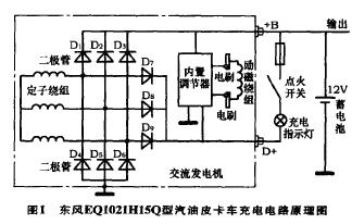
As shown in Figure 1, the diodes d1 to d6 are high-power main rectifiers, which form a 3-phase star rectifier circuit, supplying power and charging for the entire vehicle. Medium power diodes d7 ~ d9 are special rectifiers for voltage regulators and charging indication circuits. The output 14v DC voltage (d +) is isolated from the main output (+ b). When the generator is running, both + b and d + output 14v DC voltage. It can be seen from Fig. 1 that when the main rectifier tubes d1 to d3 are disconnected due to a fault and other rectifier tubes are normal, the charging indication circuit can still work normally. That is, when the d + terminal outputs a 14v DC voltage, the main output terminal (+ b) does not necessarily have an output. In this way, once the battery is depleted, the vehicle will not start (the author's company has several pickup trucks anchored in the wild due to the exhaustion of the battery, and the rescue vehicle has to send the new battery for emergency).
2. Improvement measures
It can be seen from the above analysis that the direct and reliable method to judge whether the generator is generating electricity is to detect the output charging current at the main output (+ b) terminal. The detection of the voltage at the d + terminal is only an indirect method, although in most cases the output of d + and + b are synchronized (for example, when the stator winding and rectifier d4 ~ d6 are damaged and no power is generated, d + and + b will have no output voltage simultaneously) However, the situation analyzed above is not synchronized. Once the battery is exhausted, it may cause serious consequences. Here are a few ways to improve.
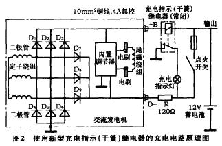
1. Development and use of new charging indication (reed) relays. The function of this (reed) relay is also to indicate the charging output of the generator, but the primary coil is connected in series with the + b terminal output circuit to directly detect the charging current (it can be called a current-type reed relay. Commonly used are Voltage type), see Figure 2. This relay has two key parameters: the rated voltage drop of the primary coil and the rated operating current of the primary coil. The resistance r provides the initial excitation current for the generator (the generator independently supplied by the regulator does not need the resistance r). This line is relatively simple.
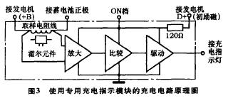
2. Develop and use a dedicated charging instruction module. This kind of module detects the charging current of the generator through the internal sampling resistance line (you can also use the Hall element to detect the magnetic field generated by the sampling resistance line), and drives the indicator light after amplification and comparison. The schematic block diagram is shown in Figure 3. This module can also be integrated into the regulator to simplify installation and increase reliability.
3. Use a charging indicator ammeter. The ammeter can indicate the charging and discharging current of the battery, which has the advantages of intuitiveness and accuracy, but the layout is difficult, the line loss is increased, and the cost is increased. Modern vehicles are rarely used.
4. Use a voltmeter. The voltmeter can monitor the battery voltage at any time, and can also intuitively reflect the battery charge and discharge conditions. According to the actual measurement, the no-load voltage of the charged battery that can successfully start the vehicle is 12.5v ~ 13v, and the battery terminal voltage can rise to 14v after the engine is running (14v voltage is limited by the generator regulator, regardless of the engine speed. At the same time, turn on Headlights and air conditioning will not cause a 14V voltage drop). If the generator cannot generate electricity, the battery terminal voltage will gradually decrease based on the no-load voltage after the engine is started (the entire vehicle power supply is taken from the battery), and there will be no increase. Therefore, the change of the battery terminal voltage before and after the operation of the generator directly reflects whether the generator is generating electricity (if the voltage rises but cannot reach 14v, it means that the generator's generating capacity is reduced and there is a fault). The voltmeter can be connected to any suitable power terminal, and the layout is flexible without increasing the line loss. At the same time, an alarm buzzer can also be set inside the voltmeter to sound an alarm when the voltage is lower than 12v.
It can be seen from the internal structure of the generator that the charging circuit must not be disconnected while the generator is running. Otherwise, the sudden large current (tens of amps) will produce abnormally high voltage across the stator windings, which will breakdown the rectifier and the regulator.
3. Practical application
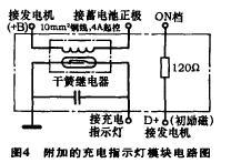
Comprehensive factors such as production difficulty, development cycle, practical effect, etc. At the same time, the improvement measures 1 and 4 are adopted, and an additional indicator module is made. The circuit is shown in FIG. 4. The operating current of the rated contact of the reed relay is set to 4a (too large a current will prevent the charging indicator from turning off at low engine speeds), which can sensitively indicate the charging current of the generator. However, this circuit using a reed relay has two disadvantages: â‘ When the generating capacity of the generator drops (a certain rectifier tube failure can only output a small current of less than 10a. It is not completely unable to charge), this circuit still indicates normal Charging (when the vehicle's electrical load is large, it will still cause the battery to lose power); â‘¡ When the battery's full voltage is close to 14v, the charging current will drop to less than 4a. At this time, the charging indicator lights up indicating that there is no charging current, which will cause people Misunderstanding that the generator cannot be charged. To this end, a voltmeter is added to the combination meter, together with the charging indicator to form a complete charging indication circuit. The working process is analyzed as follows.
1. The charging indicator lights up and the voltmeter shows that the voltage is lower than 13.8v, indicating that the generator cannot be charged (generator damage).
2. The charging indicator light goes out and the voltmeter shows that the voltage is lower than 13.8v, indicating that the generator is charging normally.
3. The charging indicator lights up and the voltmeter shows that the voltage is higher than 13.8v, indicating that the battery is full and the generator does not output an excessive charging current (generator is normal).
4. The charging indicator light is off, and the voltmeter shows that the voltage is higher than 13.8v, indicating that the damage to the generator regulator cannot limit the charging voltage, and the battery will be overcharged to cause damage (generator damage).
After loading in small batches on this line, the response was good, and the hidden danger of the accident was eliminated.
This Automation curtain is specially designed for automation industry. SDKELI LSC2 light curtain is designed for automation field, with small size, compact structure and strong anti-interference ability, and the product meets IEC 61496-2 standards. The automatic light curtain is with reliable quality and very competitive price. It has been used in many factories and has replaced curtains from Sick, Omron, Banner, Keyence, etc.
Automatic Light Curtain,Laser Light Curtain,Automation Light Beam Sensor,Automatic Infrared Beam Sensor,Infrared Beam Curttain Sensor,Infrared Beam Sensor
Jining KeLi Photoelectronic Industrial Co.,Ltd , https://www.sdkelien.com